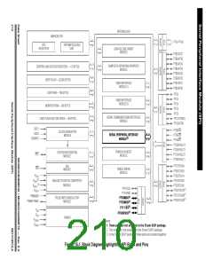
Serial Peripheral Interface Module (SPI)
Functional Description
15.4.1 Master Mode
The SPI operates in master mode when the SPI master bit, SPMSTR, is set.
NOTE:
Configure the SPI modules as master or slave before enabling them. Enable the
master SPI before enabling the slave SPI. Disable the slave SPI before disabling
the master SPI. See 15.12.1 SPI Control Register.
Only a master SPI module can initiate transmissions. Software begins the
transmission from a master SPI module by writing to the SPI data register. If the
shift register is empty, the byte immediately transfers to the shift register, setting
the SPI transmitter empty bit, SPTE. The byte begins shifting out on the MOSI pin
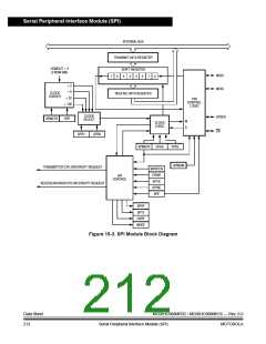
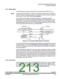
under the control of the serial clock. See Figure 15-4.
MASTER MCU
SLAVE MCU
MISO
MOSI
MISO
MOSI
SHIFT REGISTER
SHIFT REGISTER
SPSCK
SS
SPSCK
SS
BAUD RATE
GENERATOR
VDD
Figure 15-4. Full-Duplex Master-Slave Connections
The SPR1 and SPR0 bits control the baud rate generator and determine the speed
of the shift register. See 15.12.2 SPI Status and Control Register. Through the
SPSCK pin, the baud-rate generator of the master also controls the shift register of
the slave peripheral.
As the byte shifts out on the MOSI pin of the master, another byte shifts in from the
slave on the master’s MISO pin. The transmission ends when the receiver full bit,
SPRF, becomes set. At the same time that SPRF becomes set, the byte from the
slave transfers to the receive data register. In normal operation, SPRF signals the
end of a transmission. Software clears SPRF by reading the SPI status and control
register with SPRF set and then reading the SPI data register. Writing to the SPI
data register clears the SPTE bit.
15.4.2 Slave Mode
The SPI operates in slave mode when the SPMSTR bit is clear. In slave mode the
SPSCK pin is the input for the serial clock from the master MCU. Before a data
transmission occurs, the SS pin of the slave SPI must be at logic 0. SS must remain
low until the transmission is complete. See 15.6.2 Mode Fault Error.
MC68HC908MR32 • MC68HC908MR16 — Rev. 6.0
MOTOROLA Serial Peripheral Interface Module (SPI)
Data Sheet
213

 FREESCALE [ Freescale ]