Pulse-Width Modulator for Motor Control (PWMMC)
Timebase
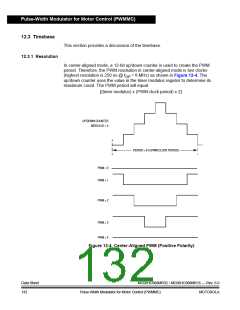
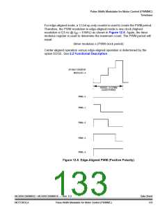
For edge-aligned mode, a 12-bit up-only counter is used to create the PWM period.
Therefore, the PWM resolution in edge-aligned mode is one clock (highest
resolution is125 ns @ fOP = 8 MHz) as shown in Figure 12-5. Again, the timer
modulus register is used to determine the maximum count. The PWM period will
equal:
(timer modulus) x (PWM clock period)
Center-aligned operation versus edge-aligned operation is determined by the
option EDGE. See 5.2 Functional Description.
UP-ONLY COUNTER
MODULUS = 4
PERIOD = 4 X (PWM
CLOCK PERIOD)
PWM = 0
PWM = 1
PWM = 2
PWM = 3
PWM = 4
Figure 12-5. Edge-Aligned PWM (Positive Polarity)
MC68HC908MR32 • MC68HC908MR16 — Rev. 6.0
MOTOROLA Pulse-Width Modulator for Motor Control (PWMMC)
Data Sheet
133

 FREESCALE [ Freescale ]