Freescale Semiconductor, Inc.
Resets and Interrupts
Resets
The state of the NOCOP bit in the CONFIG register determines whether
the COP system is enabled or disabled. To change the enable status of
the COP system, change the contents of the CONFIG register and then
perform a system reset. In the special test and bootstrap operating
modes, the COP system is initially inhibited by the disable resets (DISR)
control bit in the TEST1 register. The DISR bit can subsequently be
written to zero to enable COP resets.
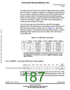
The COP timer rate control bits CR[1:0] in the OPTION register
determine the COP timeout period. The system E clock is divided by 215
and then further scaled by a factor shown in Table 10-1. After reset,
these bits are zero, which selects the shortest timeout period. In normal
operating modes, these bits can only be written once within 64 bus
cycles after reset.
Table 10-1. COP timer rate select
Divide
E/215 by
XTAL = 8MHz:
timeout(1)
16.384 ms
65.536 ms
262.14 ms
1.049 sec
XTAL = 12MHz: XTAL = 16MHz:
CR[1:0]
timeout(1)
10.923 ms
43.691 ms
174.76 ms
699.05 ms
3.0 MHz
timeout(1)
8.192 ms
32.768 ms
131.07 ms
524.29 ms
4.0 MHz
0 0
0 1
1 0
1 1
1
4
16
64
E =
2.0 MHz
1. The timeout period has a tolerance of –0/+one cycle of the E/215 clock due to the
asynchronous implementation of the COP circuitry. For example, with XTAL = 8MHz,
the uncertainty is –0/+16.384ms. See also the M68HC11 Reference Manual,
(M68HC11RM/AD).
10.3.4 COPRST — Arm/reset COP timer circuitry register
State
on reset
Address bit 7 bit 6 bit 5 bit 4 bit 3 bit 2 bit 1 bit 0
COP timer arm/reset (COPRST) $003A (bit 7) (6) (5) (4) (3) (2) (1) (bit 0)
not
affected
Complete the following reset sequence to service the COP timer. Write
$55 to COPRST to arm the COP timer clearing mechanism. Then write
$AA to COPRST to clear the COP timer. Executing instructions between
MC68HC11P2 — Rev 1.0
Technical Data
Resets and Interrupts
For More Information On This Product,
Go to: www.freescale.com

 FREESCALE [ Freescale ]