FUNCTIONAL DEVICE OPERATION
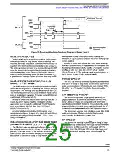
RESET AND WATCHDOG PINS, SOFTWARE WATCHDOG OPERATIONS
1. Mode 1
In both modes reset is active at device power-up and
wake-up.
2. Mode 2 (also called Safe mode)
• In mode 1–Reset is activated in case of VDD1 fall or
watchdog not triggered. WD output is active low as soon
as reset goes low. It remains low as long as the watchdog
is not properly re-activated by the SPI.
These modes are independent of the SBC modes
(Normal, Standby, Sleep, and Stop). Modes 1 and 2 selection
is achieved through the SPI (register MCR, bit SAFE). Default
mode after reset is Mode 1.
• In mode 2–(Safe mode) Reset is not activated in case of
watchdog fault. WD output has the same behavior as in
mode 1–The Watchdog output pin is a push-pull structure
driving external components of the application for signal
instance of an MCU wrong operation.
Table 5 provides Reset and Watchdog output mode
of operation. Two modes (modes 1 and 2) are available and
can be selected through the SPI Safe bit. Default operation,
after reset or power-up, is Mode 1.
33989
Analog Integrated Circuit Device Data
Freescale Semiconductor
23

 FREESCALE [ Freescale ]