FUNCTIONAL DEVICE OPERATION
OPERATIONAL MODES
When the application is in Stop mode (both MCU and
SBC), the application can wake-up from the SBC side (for
example: cyclic sense, forced wake-up, CAN message,
wake-up inputs and over current on VDD1), or the MCU side
(key wake-up, etc.).
the SBC is in Normal Request mode, the SBC goes back to
Sleep mode.
APPLICATION WAKE-UP FROM SBC SIDE
When an application is in Stop mode, it can wake-up from
the SBC side. When a wake-up is detected by the SBC (for
example, CAN, Wake-up input, etc.) the SBC turns itself into
Normal Request mode and generates an interrupt pulse at
the INT pin.
Stop mode is always selected by the SPI. In Stop mode the
software Watchdog can be running or idle depending upon
selection by the SPI (RCR, bit WDSTOP). To clear the
watchdog, the SBC must be awakened by a CS pin (SPI
wake-up). In Stop mode, SBC wake-up capability are
identical as in Sleep mode. Please refer to Table 5.
APPLICATION WAKE-UP FROM MCU SIDE
When application is in Stop mode, the wake-up event may
come from the MCU side. In this case the MCU signals to the
SBC by a low to high transition on the CS pin. Then the SBC
goes into Normal Request mode and generates an interrupt
pulse at the INT pin.
SLEEP MODE
Regulators 1 and 2 are OFF. The current from VSUP pin is
reduced. In this mode, the device can be awakened internally
by cyclic sense via the wake-up inputs pins and HS1 output,
from the forced wake-up function and from the CAN physical
interface. When a wake-up occurs the SBC goes first into
reset mode before entering Normal Request mode.
STOP MODE CURRENT MONITOR
If the VDD1 output current exceed an internal threshold
(IDD1SWU), the SBC goes automatically into Normal Request
mode and generates an interrupt at the INT pin. The interrupt
is not maskable and the interrupt register will has no flag set.
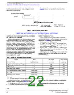
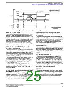
RESET MODE
In this mode, the Reset (RST) pin is low and a timer is
running for a time RSTDUR. After this time is elapsed, the SBC
enters Normal Request mode. Reset mode is entered if a
reset condition occurs (VDD1 low, watchdog timeout or
watchdog trigger in a closed window).
INTERRUPT GENERATION WHEN WAKE-UP
FROM STOP MODE
When the SBC wakes up from Stop mode, it first enters the
Normal Request mode before generating a pulse (10 µs
typical) on the INT pin. These interrupts are not maskable,
and the wake-up event can be read through the SPI registers
(CANWU bit in Reset Control Register (RCR) and LCTRx bit
in Wake-Up Register (WUR). In case of wake-up from Stop
mode over current or from forced wake-up, no bit is set. After
the INT pulse the SBC accept SPI command after a time
delay (tS1STSPI parameter).
NORMAL REQUEST MODE
This is a temporary mode automatically accessed by the
device after the reset mode, or after the SBC wake-up from
Stop mode. After wake-up from the Sleep mode or after the
device power-up, the SBC enters the Reset mode before
entering the Normal Request mode. After a wake-up from the
Stop mode, the SBC enters Normal Request mode directly.
In Normal Request mode the VDD1 regulator is ON, V2 is
OFF, the reset pin is high. As soon as the device enters the
Normal Request mode an internal 350 ms timer is started.
During these 350 ms the microcontroller of the application
must address the SBC via the SPI, configuring the Watchdog
register. This is the condition for the SBC to stop the 350 ms
timer and to go into the Normal or Standby mode and to set
the watchdog timer according to configuration.
SOFTWARE WATCHDOG IN STOP MODE
If Watchdog is enabled, the MCU has to wake-up
independently of the SBC before the end of the SBC
watchdog time. In order to do this the MCU must signal the
wake-up to the SBC through the SPI wake-up (CS activation).
The SBC then wakes up and jumps into the Normal Request
mode. MCU has to configured the SBC to go to either Normal
or Standby mode. The MCU can then decide to go back again
to Stop mode.
NORMAL REQUEST ENTERED AND NO WD
CONFIGURATION OCCURS
When there is no MCU wake-up occurring within the
watchdog timing, the SBC activates the Reset pin, jumping
into the Normal Request mode. The MCU can then be
initialized.
In case the Normal Request mode is entered after SBC
power-up, or after a wake-up from Stop mode, and if no WD
configuration occurs while the SBC is in Normal Request
mode, the SBC goes to Reset mode after the 350 ms time
period is expired before again going into Normal Request
mode. If no WD configuration is achieved, the SBC
alternatively goes from Normal Request into reset, then
Normal Request modes etc.
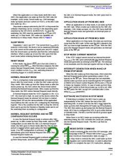
STOP MODE ENTER COMMAND
Stop mode is entered at the end of the SPI message, and
at the rising edge of the CS. Please refer to the t CSSTOP data
in Dynamic Electrical Characteristics table on page 11.
In case the Normal Request mode is entered after a wake-
up from Sleep mode, and if no WD configuration occurs while
Once Stop mode is entered the SBC could wake-up from
the V1 regulator over current detection. In order to allow time
for the MCU to complete the last CPU instruction, allowing
33989
Analog Integrated Circuit Device Data
Freescale Semiconductor
21

 FREESCALE [ Freescale ]