Reset, Stop, Mode Select, and Interrupt Timing
Table 3-7 Reset, Stop, Mode Select, and Interrupt Timing1 (continued)
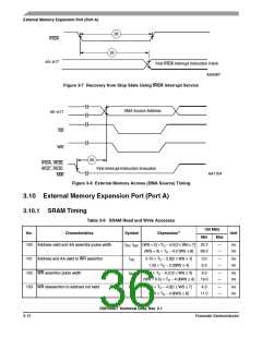
No.
Characteristics
Expression
Min
Max
Unit
21 Delay from WR assertion to interrupt request deassertion for
level sensitive fast interrupts5, 6, 7
ns
• DRAM for all WS
• SRAM WS = 1
• SRAM WS = 2, 3
• SRAM WS ≥ 4
(WS + 3.5) × TC – 10.94
N/A
—
—
—
—
Note 8
Note 8
Note 8
Note 8
1.75 × TC – 4.0
2.75 × TC – 4.0
22 Synchronous int setup time from IRQs NMI assertion to the
CLKOUT trans.
0.6 × TC – 0.1
3.9
—
ns
ns
23 Synch. int delay time from the CLKOUT trans2 to the first
external address out valid caused by first inst fetch
• Minimum
• Maximum
9.25 × TC + 1.0
24.75 × TC + 5.0
62.7
—
—
170.0
24 Duration for IRQA assertion to recover from Stop state
0.6 × TC − 0.1
3.9
—
ns
25 Delay from IRQA assertion to fetch of first instruction (when
exiting Stop)2, 8
• PLL is not active during Stop (PCTL Bit 17 = 0) and Stop PLC × ETC × PDF + (128 K
delay is enabled (OMR Bit 6 = 0) − PLC/2) × TC
• PLL is not active during Stop (PCTL Bit 17 = 0) and Stop PLC × ETC × PDF + (23.75
—
—
—
—
ms
ms
ns
delay is not enabled (OMR Bit 6 = 1)
+/- 0.5) × TC
• PLL is active during Stop (PCTL Bit 17 = 1) (Implies No
Stop Delay)
(8.25 0.5) × TC
51.7
58.3
26 Duration of level sensitive IRQA assertion to ensure interrupt
service (when exiting Stop)2, 8
• PLL is not active during Stop (PCTL Bit 17 = 0) and Stop PLC × ETC × PDF + (128 K
delay is enabled (OMR Bit 6 = 0) − PLC/2) × TC
• PLL is not active during Stop (PCTL Bit 17 = 0) and Stop PLC × ETC × PDF + (20.5
—
—
—
—
—
ms
ms
ns
delay is not enabled (OMR Bit 6 = 1)
+/- 0.5) × TC
• PLL is active during Stop (PCTL Bit 17 = 1) (implies no
Stop delay)
5.5 × TC
36.7
27 Interrupt Requests Rate
• HDI08, ESAI, ESAI_1, SHI, DAX, Timer
• DMA
ns
12TC
8TC
—
—
—
—
80.0
53.0
53.0
80.0
8TC
• IRQ, NMI (edge trigger)
• IRQ (level trigger)
12TC
DSP56367 Technical Data, Rev. 2.1
3-8
Freescale Semiconductor

 FREESCALE [ Freescale ]