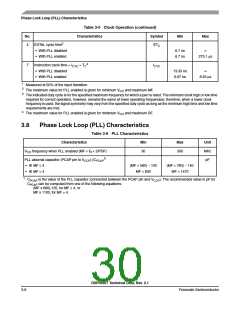
External Clock Operation
Table 3-4 Internal Clocks (continued)
Expression1, 2
Characteristics
Symbol
Min
Typ
2 × ETC
TC
Max
—
Internal clock cycle time with PLL disabled
Instruction cycle time
TC
—
—
ICYC
—
1
DF = Division Factor
Ef = External frequency
ETC = External clock cycle
MF = Multiplication Factor
PDF = Predivision Factor
TC = internal clock cycle
2
Refer to the DSP56300 Family Manual for a detailed discussion of the PLL.
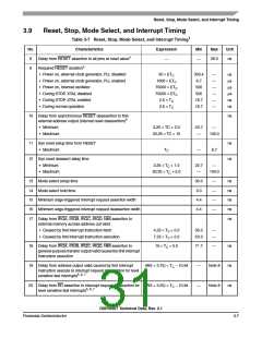
3.7
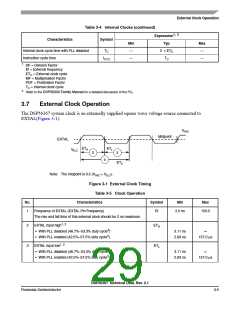
External Clock Operation
The DSP56367 system clock is an externally supplied square wave voltage source connected to
EXTAL(Figure 3-1).
VIHC
Midpoint
EXTAL
ETH
ETL
VILC
2
3
4
ETC
Note: The midpoint is 0.5 (VIHC + VILC).
Figure 3-1 External Clock Timing
Table 3-5 Clock Operation
No.
Characteristics
Symbol
Min
Max
1
Frequency of EXTAL (EXTAL Pin Frequency)
Ef
2.0 ns
150.0
The rise and fall time of this external clock should be 2 ns maximum.
2
3
EXTAL input high1, 2
• With PLL disabled (46.7%–53.3% duty cycle3)
• With PLL enabled (42.5%–57.5% duty cycle3)
ETH
ETL
3.11 ns
2.83 ns
∞
157.0 µs
EXTAL input low1, 2
• With PLL disabled (46.7%–53.3% duty cycle3)
• With PLL enabled (42.5%–57.5% duty cycle3)
3.11 ns
2.83 ns
∞
157.0 µs
DSP56367 Technical Data, Rev. 2.1
Freescale Semiconductor
3-5

 FREESCALE [ Freescale ]