Freescale Semiconductor, Inc.
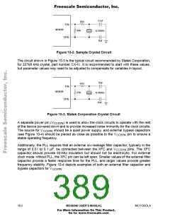
4.7 pF
330 k
XTAL
MC68340
20 M
32.768 kHz
10 pF
EXTAL
Figure 10-2. Sample Crystal Circuit
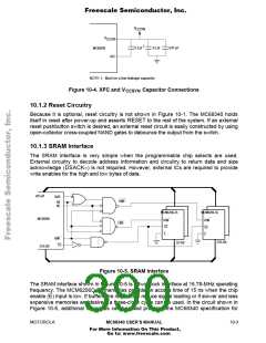
The circuit shown in Figure 10-3 is the typical circuit recommended by Statek Corporation,
for 32768 kHz crystal, part number CX-IV. It is recommended to start with these values,
but parameter values may need to be adjusted to compensate for variables in layout.
10 pF
470 k
XTAL
MC68340
22 M
32.768 kHz
20 pF
EXTAL
Figure 10-3. Statek Corporation Crystal Circuit
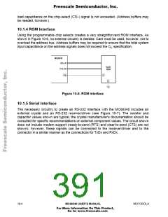
A separate power pin (V ) is used to allow the clock circuits to operate with the rest
CCSYN
of the device powered down and to provide increased noise immunity for the clock circuits.
The source for V should be a quiet power supply, and external bypass capacitors
CCSYN
(see Figure 10-4) should be placed as close as possible to the V
stable operating frequency.
pin to ensure a
CCSYN
Additionally, the PLL requires that an external low-leakage filter capacitor, typically in the
range of 0.01 to 0.1 µF, be connected between the XFC and V pins. The XFC
CCSYN
capacitor should provide 50-MΩ insulation but should not be electrolytic. For external
clock mode without PLL, the XFC pin can be left open. Smaller values of the external filter
capacitor provide a faster response time for the PLL, and larger values provide greater
frequency stability. Figure 10-4 depicts examples of both an external filter capacitor and
bypass capacitors for V
.
CCSYN
10-2
MC68340 USER’S MANUAL
MOTOROLA
For More Information On This Product,
Go to: www.freescale.com

 FREESCALE [ Freescale ]