Freescale Semiconductor, Inc.
Analog-to-Digital Converter
ATD Registers
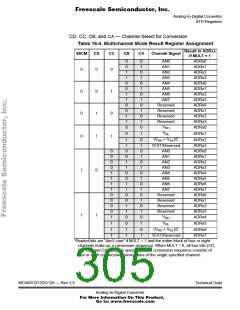
CD, CC, CB, and CA — Channel Select for Conversion
Table 16-4. Multichannel Mode Result Register Assignment
Result in ADRxx
S8CM
CD
CC
CB
CA
Channel Signal
if MULT = 1
ADRx0
ADRx1
ADRx2
ADRx3
ADRx0
ADRx1
ADRx2
ADRx3
ADRx0
ADRx1
ADRx2
ADRx3
ADRx0
0
0
1
1
0
0
1
1
0
0
1
1
0
0
1
0
1
0
1
0
1
0
1
0
1
0
AN0
AN1
0
0
0
AN2
AN3
AN4
AN5
0
0
0
1
1
0
AN6
AN7
Reserved
Reserved
Reserved
Reserved
VRH
VRL
0
1
ADRx1
0
1
1
0
1
(VRH + VRL)/2
1
1
0
0
1
1
0
0
1
1
0
0
1
1
0
0
1
0
1
0
1
0
1
0
1
0
1
0
1
0
ADRx2
ADRx3
ADRx0
ADRx1
ADRx2
ADRx3
ADRx4
ADRx5
ADRx6
ADRx7
ADRx0
ADRx1
ADRx2
ADRx3
ADRx4
TEST/Reserved
AN0
0
0
0
0
1
1
1
1
0
0
0
0
1
AN1
AN2
AN3
AN4
AN5
AN6
AN7
Reserved
Reserved
Reserved
Reserved
VRH
1
1
VRL
1
1
1
0
1
1
1
0
1
ADRx5
ADRx6
ADRx7
(VRH + VRL)/2
TEST/Reserved
Shaded bits are “don’t care” if MULT = 1 and the entire block of four or eight
channels make up a conversion sequence. When MULT = 0, all four bits (CD,
CC, CB, and CA) must be specified and a conversion sequence consists of
four or eight consecutive conversions of the single specified channel.
MC68HC912DG128 — Rev 3.0
Technical Data
Analog-to-Digital Converter
For More Information On This Product,
Go to: www.freescale.com

 FREESCALE [ Freescale ]