Freescale Semiconductor, Inc.
Analog-to-Digital Converter
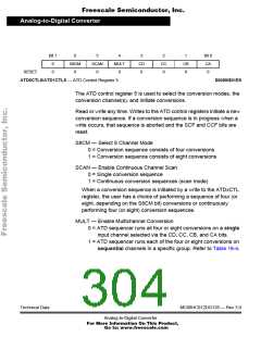
Bit 7
ADPU
0
6
AFFC
0
5
AWAI
0
4
0
0
3
0
0
2
0
0
1
ASCIE
0
Bit 0
ASCIF
0
RESET:
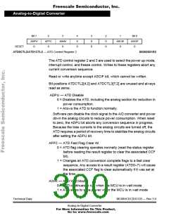
ATD0CTL2/ATD1CTL2 — ATD Control Register 2
$0062/$01E2
The ATD control register 2 and 3 are used to select the power up mode,
interrupt control, and freeze control. Writes to these registers abort any
current conversion sequence.
Read or write anytime except ASCIF bit, which cannot be written.
Bit positions ATDCTL2[4:2] and ATDCTL3[7:2] are unused and always
read as zeros.
ADPU — ATD Disable
0 = Disables the ATD, including the analog section for reduction in
power consumption.
1 = Allows the ATD to function normally.
Software can disable the clock signal to the A/D converter and power
down the analog circuits to reduce power consumption. When reset
to zero, the ADPU bit aborts any conversion sequence in progress.
Because the bias currents to the analog circuits are turned off, the
ATD requires a period of recovery time to stabilize the analog circuits
after setting the ADPU bit.
AFFC — ATD Fast Flag Clear All
0 = ATD flag clearing operates normally (read the status register
before reading the result register to clear the associated CCF
bit).
1 = Changes all ATD conversion complete flags to a fast clear
sequence. Any access to a result register (ATD0–7) will cause
the associated CCF flag to clear automatically if it was set at
the time.
AWAI — ATD Wait Mode
0 = ATD continues to run when the MCU is in wait mode
1 = ATD stops to save power when the MCU is in wait mode
Technical Data
MC68HC912DG128 — Rev 3.0
Analog-to-Digital Converter
For More Information On This Product,
Go to: www.freescale.com

 FREESCALE [ Freescale ]