Freescale Semiconductor, Inc.
Clock Functions
EXTAL
LOCK
LOCK
DETECTOR
REFDV <2:0>
REDUCED
CONSUMPTION
OSCILLATOR
REFERENCE
PROGRAMMABLE
DIVIDER
REFCLK
DIVCLK
UP
PDET
PHASE
DETECTOR
XTAL
CPUMP
VCO
DOWN
EXTALi
VDDPLL
SLOW MODE
PROGRAMMABLE
CLOCK DIVIDER
LOOP
PROGRAMMABLE
DIVIDER
SLWCLK
LOOP
FILTER
XFC
PAD
÷2
× 2
SLDV <5:0>
SYN <5:0>
EXTALi
PLLCLK
XCLK
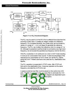
Figure 11-2. PLL Functional Diagram
The PLL may be used to run the MCU from a different time base than the
incoming crystal value. It creates an integer multiple of a reference
frequency. For increased flexibility, the crystal clock can be divided by
values in a range of 1 – 8 (in unit steps) to generate the reference
frequency. The PLL can multiply this reference clock in a range of 1 to
64. Although it is possible to set the divider to command a very high clock
frequency, do not exceed the specified bus frequency limit for the MCU.
If the PLL is selected, it will continue to run when in WAIT mode resulting
in more power consumption than normal. To take full advantage of the
reduced power consumption of WAIT mode, turn off the PLL before
going into WAIT. Please note that in this case the PLL stabilization time
applies.
The PLL operation is suspended in STOP mode. After STOP exit
followed by the stabilization time, it resumes operation at the same
frequency, provided the AUTO bit is set.
A passive external loop filter must be placed on the control line (XFC
pad). The filter is a second-order, low-pass filter to eliminate the VCO
input ripple. Values of components in the diagram are dependent upon
the desired VCO operation. See XFC description.
Technical Data
MC68HC912DG128 — Rev 3.0
Clock Functions
For More Information On This Product,
Go to: www.freescale.com

 FREESCALE [ Freescale ]