Table 2-2 Signal and Package Information for the 160-Pin LQFP and MBGA (Continued)
State
During
Reset
Signal
Name
Pin
No.
Ball No.
Type
Signal Description
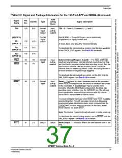
EXTBOOT
124
B11
Schmitt
Input
Input,
pull-up
enabled
External Boot — This input is tied to VDD to force the device to
boot from off-chip memory (assuming that the on-chip Flash
memory is not in a secure state). Otherwise, it is tied to ground.
For details, see Table 4-4.
Note: When this pin is tied low, the customer boot software
should disable the internal pull-up resistor by setting the XBOOT
bit of the SIM_PUDR; see Part 6.5.6.
EMI_MODE
159
B2
Schmitt
Input
Input,
pull-up
enabled
External Memory Mode — This input is tied to VDD in order to
enable an extra four address lines, for a total of 20 address lines
out of reset. This function is also affected by EXTBOOT and the
Flash security mode. For details, see Table 4-4.
If a 20-bit address bus is not desired, then this pin is tied to
ground.
Note: When this pin is tied low, the customer boot software
should disable the internal pull-up resistor by setting the
EMI_MODE bit of the SIM_PUDR; see Part 6.5.6.
56F8367 Technical Data, Rev. 9
38
Freescale Semiconductor
Preliminary

 FREESCALE [ Freescale ]