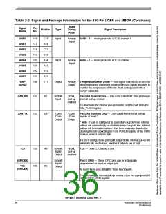
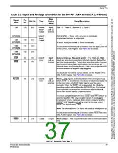
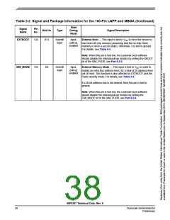
Table 2-2 Signal and Package Information for the 160-Pin LQFP and MBGA (Continued)
State
During
Reset
Signal
Name
Pin
No.
Ball No.
Type
Signal Description
ANB0
ANB1
ANB2
ANB3
ANB4
ANB5
ANB6
ANB7
116
117
118
119
120
121
122
123
108
C13
B14
C12
B13
A14
A13
B12
A12
E11
Input
Analog
Input
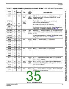
ANB0 - 3 — Analog inputs to ADC B, channel 0
Input
Analog
Input
ANB4 - 7 — Analog inputs to ADC B, channel 1
TEMP_
SENSE
Output
Analog
Output
Temperature Sense Diode — This signal connects to an on-chip
diode that can be connected to one of the ADC inputs and used to
monitor the temperature of the die. Must be bypassed with a
0.01μF capacitor.
CAN_RX
CAN_TX
143
142
B7
D6
Schmitt
Input
Input,
pull-up
enabled
FlexCAN Receive Data — This is the CAN input. This pin has an
internal pull-up resistor.
To deactivate the internal pull-up resistor, set the CAN bit in the
SIM_PUDR register.
Open
Drain
Open
Drain
FlexCAN Transmit Data — CAN output with internal pull-up
enable at reset.*
Output
Output
* Note: If a pin is configured as open drain output mode, internal
pull-up will automatically be disabled when it outputs low. Internal
pull-up will be enabled unless it has been manually disabled by
clearing the corresponding bit in the PUREN register of the GPIO
module, when it outputs high.
If a pin is configured as push-pull output mode, internal pull-up will
automatically be disabled, whether it outputs low or high.
TC0
133
135
A9
B9
Schmitt
Input/
Output
Input,
pull-up
enabled
TC0 — Timer C, Channel 0 and 1
(GPIOE8)
Schmitt
Input/
Output
Port E GPIO — These GPIO pins can be individually
programmed as input or output pins.
TC1
(GPIOE9)
At reset, these pins default to Timer functionality.
To deactivate the internal pull-up resistor, clear the appropriate bit
of the GPIOE_PUR register.
56F8367 Technical Data, Rev. 9
36
Freescale Semiconductor
Preliminary

 FREESCALE [ Freescale ]