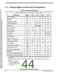
3.11 Analog-to-Digital Converter (ADC) Characteristics
Table 3-16 ADC Characteristics
Operating Conditions: VSS = VSSA = 0 V, VDD = VDDA = 3.0–3.6 V, VREF = VDD-0.3V, ADCDIV = 4, 9, or 14, (for optimal performance),
ADC clock = 4MHz, 3.0–3.6 V, TA = –40° to +85°C, CL ≤ 50pF, fOP = 80MHz
Characteristic
ADC input voltages
Symbol
Min
Typ
Max
Unit
2
01
12
—
—
VREF
VADCIN
—
V
Resolution
RES
INL
—
12
Bits
Integral Non-Linearity3
Differential Non-Linearity
LSB4
LSB4
+/- 2.5
+/- 0.9
+/- 4
+/- 1
DNL
Monotonicity
GUARANTEED
—
ADC internal clock5
Conversion range
fADIC
RAD
tADC
0.5
VSSA
—
5
MHz
V
—
6
VDDA
—
tAIC cycles6
tAIC cycles6
Conversion time
Sample time
tADS
—
1
—
pF6
—
Input capacitance
CADI
EGAIN
THD
—
0.93
60
5
1.00
64
—
1.08
—
Gain Error (transfer gain)5
Total Harmonic Distortion5
Offset Voltage5
VOFFSET
SINAD
ENOB
SFDR
-90
55
-25
60
+10
—
mV
—
Signal-to-Noise plus Distortion5
Effective Number of Bits5
9
10
—
bit
Spurious Free Dynamic Range5
Bandwidth
65
70
—
dB
BW
—
—
100
50
—
—
KHz
mA
ADC Quiescent Current (each dual ADC)
IADC
V
REF Quiescent Current (each dual ADC)
IVREF
—
12
16.5
mA
1. For optimum ADC performance, keep the minimum VADCIN value > 25mV. Inputs less than 25mV may convert to a digital
output code of 0.
2. VREF must be equal to or less than VDDA and must be greater than 2.7V. For optimal ADC performance, set VREF to
V
DDA-0.3V.
3. Measured in 10-90% range.
4. LSB = Least Significant Bit.
5. Guaranteed by characterization.
6. tAIC = 1/fADIC
56F807 Technical Data Technical Data, Rev. 16
44
Freescale Semiconductor

 FREESCALE [ Freescale ]