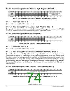
5.6.11 Fast Interrupt 0 Vector Address High Register (FIVAH0)
Base + $A
Read
15
0
14
0
13
0
12
0
11
0
10
0
9
0
8
0
7
0
6
0
5
0
4
3
2
1
0
0
FAST INTERRUPT 0 VECTOR
ADDRESS HIGH
Write
RESET
0
0
0
0
0
0
0
0
0
0
0
0
0
0
0
Figure 5-13 Fast Interrupt 0 Vector Address High Register (FIVAH0)
5.6.11.1 Reserved—Bits 15–5
This bit field is reserved. Each bit must be set to 0.
5.6.11.2 Fast Interrupt 0 Vector Address High (FIVAH0)—Bits 4–0
The upper five bits of the vector address used for Fast Interrupt 0. This register is combined with FIVAL0
to form the 21-bit vector address for Fast Interrupt 0 defined in the FIM0 register.
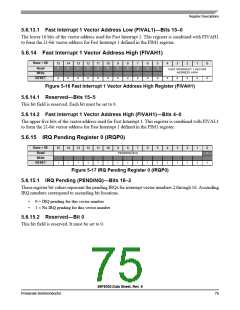
5.6.12 Fast Interrupt 1 Match Register (FIM1)
Base + $B
Read
15
0
14
0
13
0
12
0
11
0
10
0
9
0
8
0
7
0
6
0
5
0
4
0
3
2
1
0
0
0
FAST INTERRUPT 1
Write
0
0
0
0
0
0
0
0
0
0
0
0
RESET
Figure 5-14 Fast Interrupt 1 Match Register (FIM1)
5.6.12.1 Reserved—Bits 15–6
This bit field is reserved. Each bit must be set to 0.
5.6.12.2 Fast Interrupt 1 Vector Number (FAST INTERRUPT 1)—Bits 5–0
These values determine which IRQ will be Fast Interrupt 1. Fast Interrupts vector directly to a service
routine based on values in the Fast Interrupt Vector Address registers without having to go to a jump table
first. IRQs used as Fast Interrupts must be set to priority level 2. Unexpected results will occur if a Fast
Interrupt vector is set to any other priority. A Fast Interrupt automatically becomes the highest priority
level 2 interrupt, regardless of its location in the interrupt table prior to being declared as Fast Interrupt.
Fast Interrupt 0 has priority over Fast Interrupt 1. To determine the vector number of each IRQ, refer to
the vector table.
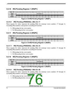
5.6.13 Fast Interrupt 1 Vector Address Low Register (FIVAL1)
Base + $C
Read
15
14
13
12
11
10
9
8
7
6
5
4
3
2
0
1
0
0
0
FAST INTERRUPT 1 VECTOR ADDRESS LOW
Write
0
0
0
0
0
0
0
0
0
0
0
0
0
RESET
Figure 5-15 Fast Interrupt 1 Vector Address Low Register (FIVAL1)
56F8036 Data Sheet, Rev. 6
74
FreescaleSemiconductor

 FREESCALE [ Freescale ]