Register Descriptions
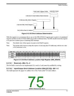
Instruction Portion
“Hard Coded” Address Portion
6 Bits from I/O Short Address Mode Instruction
16 Bits from SIM_IOSALO Register
2 bits from SIM_IOSAHI Register
Full 24-Bit for Short I/O Address
Figure 6-12 I/O Short Address Determination
With this register set, an interrupt driver can set the SIM_IOSALO register pair to point to its peripheral
registers and then use the I/O Short addressing mode to reference them. The ISR should restore this register
to its previous contents prior to returning from interrupt.
Note:
Note:
The default value of this register set points to the EOnCE registers.
The pipeline delay between setting this register set and using short I/O addressing with the new value
is five instruction cycles.
Base + $D
Read
15
14
13
12
11
10
9
8
7
6
5
4
3
2
1
0
0
0
0
0
0
0
0
0
0
0
0
0
0
0
ISAL[23:22]
Write
0
0
0
0
0
0
0
0
0
0
0
0
0
0
1
1
RESET
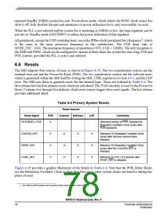
Figure 6-13 I/O Short Address Location High Register (SIM_IOSAHI)
6.3.10.1 Reserved—Bits 15—2
This bit field is reserved or not implemented. It is read as 0 and cannot be modified by writing.
6.3.10.2 Input/Output Short Address Location (ISAL[23:22])—Bit 1–0
This field represents the upper two address bits of the “hard coded” I/O short address.
56F8014 Technical Data, Rev. 9
Freescale Semiconductor
Preliminary
75

 FREESCALE [ Freescale ]