required Standby 200kHz system bus rate. Power-down mode, which selects the ROSC clock source but
shuts it off, fully disables the part and minimizes its power utilization but is only recoverable via reset.
When the PLL is not selected and the system bus is operating at 200kHz or less, the large regulator can be
put into its Standby mode (LRSTDBY) to reduce the power utilization of that regulator.
1
All peripherals, except the COP/watchdog timer, run at the IPBus clock (peripheral bus) frequency , which
is the same as the main processor frequency in this architecture. The COP timer runs at
MSTR_OSC / 1024. The maximum frequency of operation is SYS_CLK = 32MHz. The only exception is
the TMR and PWM, which can be configured to operate at three times the system bus rate using TCR and
PCR controls, provided the PLL is active and selected.
6.6 Resets
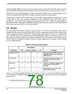
The SIM supports four sources of reset, as shown in Figure 6-15. The two asynchronous sources are the
external reset pin and the Power-On Reset (POR). The two synchronous sources are the software reset,
which is generated within the SIM itself by writing the SIM_CTRL register in Section 6.3.1, and the COP
reset. The SIM uses these to generate resets for the internal logic. These are outlined in Table 6-4. The
first column lists the four primary resets which are calculated. The JTAG circuitry is reset by the Power-On
Reset. Columns two through five indicate which reset sources trigger these reset signals. The last column
provides additional detail.
Table 6-4 Primary System Resets
Reset Sources
Reset Signal
POR
External
Software
COP
Comments
EXTENDED_POR
X
Stretched version of POR. Relevant 64
Relaxation Oscillator Clock cycles after
POR deasserts.
CLKGEN_RST
PERIP_RST
CORE_RST
X
X
X
X
X
X
X
X
X
X
X
X
Released 32 Relaxation Oscillator Clock
cycles after all reset sources have
released.
Releases 32 Relaxation Oscillator Clock
cycles after the CLKGEN_RST is
released.
Releases 32 SYS_CLK periods after
PERIP_RST is released.
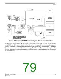
Figure 6-15 provides a graphic illustration of the details in Table 6-4. Note that the POR_Delay blocks
use the Relaxation Oscillator Clock as their time base since other system clocks are inactive during this
phase of reset.
1. The TMR ans PWM modules can be operated at three times the IPBus clock frequency.
56F8014 Technical Data, Rev. 9
78
Freescale Semiconductor
Preliminary

 FREESCALE [ Freescale ]