RC4200
PRODUCT SPECIFICATION
Electrical Characteristics (continued)
(Over operating temperature range, V = -15V unless otherwise noted)
S
4200A
4200
Parameters
Test Conditlons
Min.
Typ.
Max. Min.
Typ.
Max. Units
Frequency Response,
-3dB point
Supply Voltage
4.0
-15
4.0
-15
MHz
V
-18
-9.0 -18
4.0
-9.0
4.0
Supply Current
I = I = I = 150 µA
mA
1
2
4
T = +25°C
A
Notes:
1. Refer to Figure 6 for example.
2. The input circuits tend to become unstable at I , I , I < 50 µA and linearity decreases when I , I , I > 250 µA
1
2
4
1 2 4
(eq. @ I = I = 500 µA, nonlinearity error ≈ 0.5%).
1
2
3. These specifications apply with output (I ) connected to an op amp summing junction. If desired, the output (I ) at pin (4) can
3
3
be used to drive a resistive load directly. The resistive load should be less than 700Ω and must be pulled up to a positive
supply such that the voltage on pin (4) stays within a range of 0 to +5V.
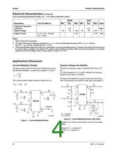
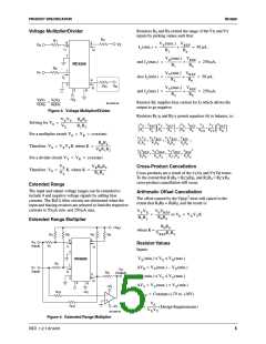
Applications Discussion
Current Multiplier/ Divider
Dynamic Range and Stability
The basic design criteria for all circuit configurations using
the RC4200 multiplier is contained in equation (1), that is,
The precision dynamic range for the RC4200 is from +50
µA
to +250 µA inputs for I , I and I . Stability and accuracy
degrade if this range is exceeded.
1
2
4
I1I2
I3 = ---------
I4
To improve the stability for input currents less than 50 µA,
The current-product-balance equation restates this as:
filter circuits (R C ) are added to each input (see Figure 2).
S S
I1I2 = I3I4 (6)
R
4
R
1
8
5
+V
Z
V
X
I
I
4
1
R
S
R
S
R
Z
4
R
1
7
8
5
V
V
X
Y
C
S
C
S
+
+
+
RC4200
I
I
I
1
4
+V
Z
R
2
V
R
X
7
1
1
2
I
=
1
V
I
=
V
4
Y
1
R
4
I
2
R
RC4200
O
4
R
S
V
O
R
2
I
3
+V
S
3
S
6
C
S
Ammeter
A
2
–
4
A1
V
R
–V
Y
I
=
2
2
+
2
I
3
3
6
–V
S
R
C
= 10k Ohms
= 0.005 µF
S
S
65-4200-02
65-4200-03
–V
S
Figure 2. Current Multiplier/Divider with Filters
Figure 1. Current Multiplier/Divider
Amplifier A1 is used to convert the I current to an output
3
voltage.
Multiplier: Vz = constant ≠ 0
Divider: Vy = constant ≠ 0
4
REV. 1.2.1 6/14/01

 FAIRCHILD [ FAIRCHILD SEMICONDUCTOR ]