PRODUCT SPECIFICATION
FAN5066
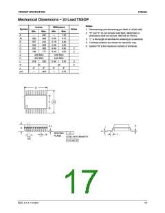
Mechanical Dimensions – 20 Lead TSSOP
Notes:
Inches
Millimeters
Min. Max.
Symbol
Notes
1. Dimensioning and tolerancing per ANSI Y14.5M-1982.
Min.
Max.
2. "D" and "E" do not include mold flash. Mold flash or
protrusions shall not exceed .006 inch (0.15mm).
A
—
.047
.006
.012
.008
.260
.177
—
1.20
0.15
0.30
0.20
6.60
4.50
A1
B
.002
.007
.004
.252
.169
0.05
0.19
0.09
6.40
4.30
3. "L" is the length of terminal for soldering to a substrate.
4. Terminal numbers are shown for reference only.
5. Symbol "N" is the maximum number of terminals.
C
D
E
2
2
e
.026 BSC
.252 BSC
.018 .030
0.65 BSC
6.40 BSC
0.45 0.75
H
L
3
5
N
α
20
20
0°
8°
0°
8°
ccc
—
.004
—
0.10
D
E
H
C
A1
A
α
SEATING
PLANE
– C –
L
B
LEAD COPLANARITY
ccc C
e
REV. 2.1.4 11/13/01
17

 FAIRCHILD [ FAIRCHILD SEMICONDUCTOR ]