FAN5066
PRODUCT SPECIFICATION
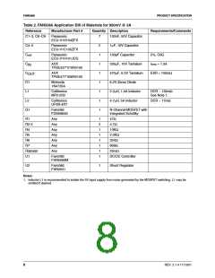
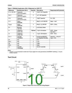
Table 3. FAN5066 Application Bill of Materials for DDR VTT
Reference
Manufacturer Part #
Quantity Description
Requirements/Comments
C1–2, C6–C9
Panasonic
ECU-V1H104ZFX
6
2
1
1
4
1
100nF, 50V Capacitor
C4–5
C10
Panasonic
ECU-V1C105ZFX
1µF, 16V Capacitor
100pF Capacitor
Panasonic
ECU-V1H101JCG
5%, C0G
C11
Sanyo
6SP680M
680µF, 6.3V OSCON
820µF, 4V OSCON
6.2V Zener Diode
I
= 4.8A
RMS
C
Sanyo
4SP820M
ESR < 12mΩ
OUT
D1
Motorola
1N4735A
L1
Coiltronics
UP1B-1R5
Optional 1.5µH, 4A Inductor
DCR ~ 20mΩ
See Note 1.
L2
Coiltronics
UP4B-1R5
1
2
1.5µH, 13A Inductor
DCR ~ 4mΩ
Q1–2
Fairchild
FDS6680S
N-Channel MOSFET
w/ Integrated Schottky
R
= 17mΩ @
DS(ON)
V = 4.5V
GS
R1
Any
Any
Any
Any
1
2
1
2
1
47Ω
R2-3
R4
4.7Ω
10KΩ
R5-6
U1
499Ω
Fairchild
DC/DC Controller
FAN5066M
Notes:
1. Inductor L1 is recommended to isolate the 5V input supply from noise generated by the MOSFET switching. L1 may be
omitted if desired.
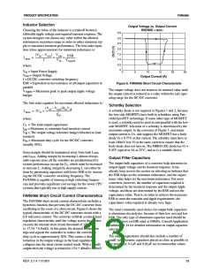
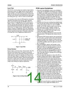
Test Circuit
+12V
47Ω
1µF
t
t
F
R
VCCQP
HIDRV
90%
50%
90%
50%
4.7Ω
4.7Ω
HIDRV
+5V
VCCA
VCCP
0.1µF
1µF
3000pF
3000pF
10%
10%
t
t
DT2
DT1
LODRV
50%
50%
LODRV
GNDA GNDD GNDP
Figure 3. Output Drive Test Circuit and Timing Diagram
10
REV. 2.1.4 11/13/01

 FAIRCHILD [ FAIRCHILD SEMICONDUCTOR ]