PRODUCT SPECIFICATION
FAN5066
Inductor Selection
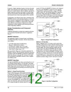
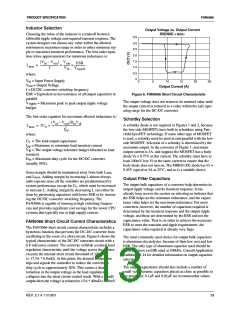
Output Voltage vs. Output Current
Choosing the value of the inductor is a tradeoff between
allowable ripple voltage and required transient response. The
system designer can choose any value within the allowed
minimum to maximum range in order to either minimize rip-
ple or maximize transient performance. The first order equa-
tion (close approximation) for minimum inductance is:
RSENSE = 6mΩ
3.5
3.0
2.5
2.0
1.5
1.0
(Vin – Vout
)
Vout
ESR
------------------------------ ---------- -----------------
Lmin
=
×
×
f
Vin Vripple
0.5
0
where:
V
= Input Power Supply
in
0
5
10
15
20
25
V
out
= Output Voltage
Output Current (A)
f = DC/DC converter switching frequency
ESR = Equivalent series resistance of all output capacitors in
parallel
Figure 6. FAN5066 Short Circuit Characteristic
The output voltage does not return to its nominal value until
the output current is reduced to a value within the safe oper-
ating range for the DC-DC converter
V
= Maximum peak to peak output ripple voltage
ripple
budget.
The first order equation for maximum allowed inductance is:
Schottky Selection
(Vin – Vout)D Vtb
------------------------------------m------------
×
A schottky diode is not required in Figures 1 and 2, because
the low-side MOSFETs have built in schottkies using Fair-
child SyncFET technology. If some other type of MOSFET
is used, a schottky must be used in anti-parallel with the low-
side MOSFET. Selection of a schottky is determined by the
maximum output. In the converter of Figure 1, maximum
output current is 3A, and suppose the MOSFET has a body
Lmax = 2CO
I2PP
where:
C
= The total output capacitance
o
I
= Maximum to minimum load transient current
= The output voltage tolerance budget allocated to load
pp
V
tb
transient
= Maximum duty cycle for the DC/DC converter
diode V = 0.75V at this current. The schottky must have at
f
D
m
least 100mV less V at the same current to ensure that the
f
(usually 95%).
body diode does not turn on. The MBRS130L diode has V =
f
0.45V typical at 3A at 25°C, and so is a suitable choice.
Some margin should be maintained away from both L
min
and L
. Adding margin by increasing L almost always
max
Output Filter Capacitors
adds expense since all the variables are predetermined by
The output bulk capacitors of a converter help determine its
output ripple voltage and its transient response. It has
already been seen in the section on selecting an inductor that
the ESR helps set the minimum inductance, and the capaci-
tance value helps set the maximum inductance. For most
converters, however, the number of capacitors required is
determined by the transient response and the output ripple
voltage, and these are determined by the ESR and not the
capacitance value. That is, in order to achieve the necessary
ESR to meet the transient and ripple requirements, the
capacitance value required is already very large.
system performance except for C , which must be increased
o
to increase L. Adding margin by decreasing L can either be
done by purchasing capacitors with lower ESR or by increas-
ing the DC/DC converter switching frequency. The
FAN5066 is capable of running at high switching frequen-
cies and provides significant cost savings for the newer CPU
systems that typically run at high supply current.
FAN5066 Short Circuit Current Characteristics
The FAN5066 short circuit current characteristic includes a
hysteresis function that prevents the DC-DC converter from
oscillating in the event of a short circuit. Figure 6 shows the
typical characteristic of the DC-DC converter circuit with a
6.8 mΩ sense resistor. The converter exhibits a normal load
regulation characteristic until the voltage across the resistor
exceeds the internal short circuit threshold of 120mV
(= 17.5A * 6.8mΩ). At this point, the internal comparator
trips and signals the controller to reduce the converter’s
duty cycle to approximately 20%. This causes a drastic
reduction in the output voltage as the load regulation
collapses into the short circuit control mode. With a 40mΩ
output short,the voltage is reduced to 15A * 40mΩ = 600mV.
The most commonly used choice for output bulk capacitors
is aluminum electrolytics, because of their low cost and low
ESR. The only type of aluminum capacitor used should be
those that have an ESR rated at 100kHz. Consult Application
Bulletin AB-14 for detailed information on output capacitor
selection.
The output capacitance should also include a number of
small value ceramic capacitors placed as close as possible to
the processor; 0.1µF and 0.01µF are recommended values.
REV. 2.1.4 11/13/01
13

 FAIRCHILD [ FAIRCHILD SEMICONDUCTOR ]