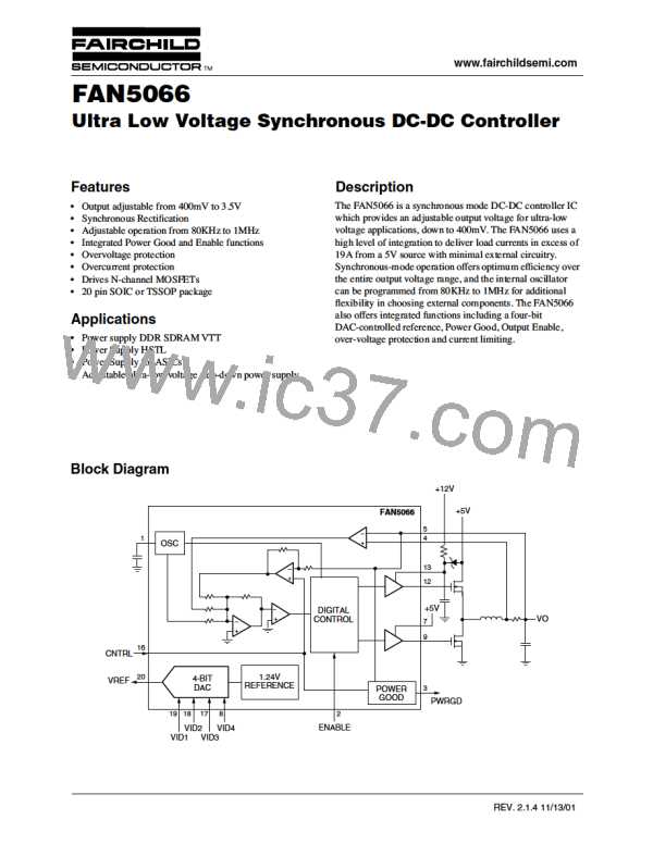
FAN5066
PRODUCT SPECIFICATION
Mechanical Dimensions – 20 Lead SOIC
Notes:
Inches
Millimeters
Symbol
Notes
1. Dimensioning and tolerancing per ANSI Y14.5M-1982.
Min.
Max.
Min.
Max.
2. "D" and "E" do not include mold flash. Mold flash or
protrusions shall not exceed .010 inch (0.25mm).
A
.093
.004
.013
.009
.496
.291
.104
.012
.020
.013
.512
.299
2.35
0.10
0.33
0.23
12.60
7.40
2.65
0.30
0.51
0.32
13.00
7.60
A1
B
3. "L" is the length of terminal for soldering to a substrate.
4. Terminal numbers are shown for reference only.
5. "C" dimension does not include solder finish thickness.
6. Symbol "N" is the maximum number of terminals.
C
D
E
5
2
2
e
.050 BSC
1.27 BSC
H
h
.394
.010
.016
.419
.029
.050
10.00
0.25
0.40
10.65
0.75
1.27
L
3
6
N
α
20
20
0°
8°
0°
8°
ccc
—
.004
—
0.10
20
11
E
H
1
10
h x 45°
D
C
A1
A
α
SEATING
PLANE
– C –
e
B
L
LEAD COPLANARITY
ccc C
16
REV. 2.1.4 11/13/01

 FAIRCHILD [ FAIRCHILD SEMICONDUCTOR ]