XRT86L30
SINGLE T1/E1/J1 FRAMER/LIU COMBO
REV. 1.0.1
12.5
E1 Brief discussion of alarms and error conditions
As defined in E1 specification, alarm conditions are created from defects. Defects are momentary impairments
present on the E1 trunk. If a defect is present for a sufficient amount of time (called the integration time), then
the defect becomes an alarm. Once an alarm is declared, the alarm is present until after the defect clears for a
sufficient period of time. The time it takes to clear an alarm is called the de-integration time.
Alarms are used to detect and warn maintenance personnel of problems on the E1 trunk. There are three
types of alarms:
•
•
•
Red alarm or Service Alarm Indication (SAI) Signal
Blue alarm or Alarm Indication Signal (AIS)
Yellow alarm or Remote Alarm Indication (RAI) Signal
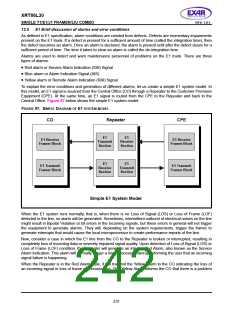
To explain the error conditions and generation of different alarms, let us create a simple E1 system model. In
this model, an E1 signal is sourced from the Central Office (CO) through a Repeater to the Customer Premises
Equipment (CPE). At the same time, an E1 signal is routed from the CPE to the Repeater and back to the
Central Office. Figure 97 below shows the simple E1 system model.
FIGURE 97. SIMPLE DIAGRAM OF E1 SYSTEM MODEL
CO
Repeater
CPE
E1
Transmit
Section
E1
Receive
Section
E1 Receive
Framer Block
E1 Receive
Framer Block
E1
Receive
Section
E1
Transmit
Section
E1 Transmit
Framer Block
E1 Transmit
Framer Block
Simple E1 System Model
When the E1 system runs normally, that is, when there is no Loss of Signal (LOS) or Loss of Frame (LOF)
detected in the line, no alarm will be generated. Sometimes, intermittent outburst of electrical noises on the line
might result in Bipolar Violation or bit errors in the incoming signals, but these errors in general will not trigger
the equipment to generate alarms. They will, depending on the system requirements, trigger the framer to
generate interrupts that would cause the local microprocessor to create performance reports of the line.
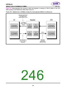
Now, consider a case in which the E1 line from the CO to the Repeater is broken or interrupted, resulting in
completely loss of incoming data or severely impaired signal quality. Upon detection of Loss of Signal (LOS) or
Loss of Frame (LOF) condition, the Repeater will generate an internal Red Alarm, also known as the Service
Alarm Indication. This alarm will normally trigger a microprocessor interrupt informing the user that an incoming
signal failure is happening.
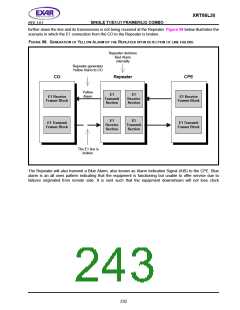
When the Repeater is in the Red Alarm state, it will transmit the Yellow Alarm to the CO indicating the loss of
an incoming signal or loss of frame synchronization. This Yellow Alarm informs the CO that there is a problem
231

 EXAR [ EXAR CORPORATION ]