XRT86L30
SINGLE T1/E1/J1 FRAMER/LIU COMBO
REV. 1.0.1
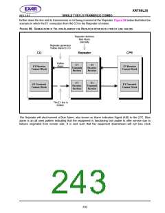
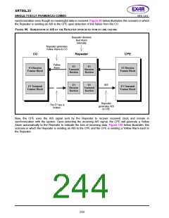
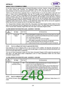
synchronization even though no meaningful data is received. Figure 99 below illustrates this scenario in which
the Repeater is sending an AIS to the CPE upon detection of line failure from the CO.
FIGURE 99. GENERATION OF AIS BY THE
R
EPEATER UPON DETECTION OF LINE FAILURE
Repeater declares
Red Alarm
internally
Repeater generates
Yellow Alarm to CO
CO
Repeater
CPE
Yellow
Alarm
E1
Transmit
Section
E1
Receive
Section
E1 Receive
Framer Block
E1 Receive
Framer Block
AIS
E1
Receive
Section
E1
Transmit
Section
E1 Transmit
Framer Block
E1 Transmit
Framer Block
Repeater
generates AIS
to CPE
The E1 line is
broken
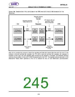
Now, the CPE uses the AIS signal sent by the Repeater to recover received clock and remain in
synchronization with the system. Upon detecting the incoming AIS signal, the CPE will generate a Yellow
Alarm automatically to the Repeater to indicate the loss of incoming data. Figure 100 below illustrates this
scenario in which the Repeater is sending an AIS to the CPE and the CPE is sending a Yellow Alarm back to
the Repeater.
233

 EXAR [ EXAR CORPORATION ]