XRT86L30
REV. 1.0.1
SINGLE T1/E1/J1 FRAMER/LIU COMBO
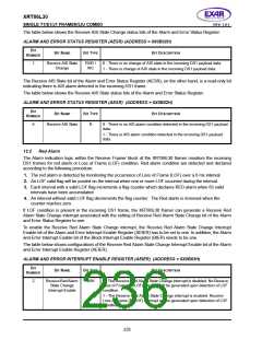
The table below shows the Receive Yellow Alarm State Change status bits of the Alarm and Error Status
Register.
ALARM AND ERROR STATUS REGISTER (AESR)(ADDRESS = 0X0B02H)
B
IT
B
IT
N
AME
B
IT
TYPE
BIT DESCRIPTION
N
UMBER
0
Receive Yellow
Alarm State
Change
RUR /
WC
0 - There is no change of Yellow Alarm state in the incoming DS1 payload
data.
1 - There is change of Yellow Alarm state in the incoming DS1 payload
data.
The table below shows the Receive AIS State Change status bits of the Alarm and Error Status Register.
The Receive Yellow Alarm State bit of the Alarm and Error Status Register (AESR), on the other hand, is a
read-only bit indicating there is Yellow Alarm detected in the incoming DS1 frame.
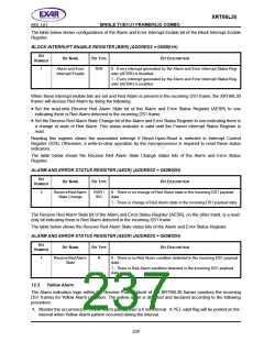
The table below shows the Receive Yellow Alarm State status bits of the Alarm and Error Status Register.
ALARM AND ERROR STATUS REGISTER (AESR) (ADDRESS = 0X0B02H)
B
IT
B
IT
N
AME
B
IT
TYPE
BIT DESCRIPTION
N
UMBER
5
Receive Yellow
Alarm State
R
0 - There is no Yellow Alarm condition detected in the incoming DS1 pay-
load data.
1 - There is Yellow Alarm condition detected in the incoming DS1 payload
data.
12.4
Bipolar Violation
The line coding for the DS1 signal should be bipolar. That is, a binary "0" is transmitted as zero volts while a
binary "1" is transmitted as either a positive or negative pulse, opposite in polarity to the previous pulse. A
Bipolar Violation or BPV occurs when the alternate polarity rule is violated. The Alarm indication logic within the
Receive Framer block of the XRT86L30 framer monitors the incoming DS1 frames for Bipolar Violations.
If a Bipolar Violation is present in the incoming DS1 frame, the XRT86L30 framer can generate a Receive
Bipolar Violation interrupt associated with the setting of Receive Bipolar Violation bit of the Alarm and Error
Status Register to one.
To enable the Receive Bipolar Violation interrupt, the Receive Bipolar Violation Interrupt Enable bit of the Alarm
and Error Interrupt Enable Register (AEIER) has to be set to one. In addition, the Alarm and Error Interrupt
Enable bit of the Block Interrupt Enable Register (BIER) needs to be one.
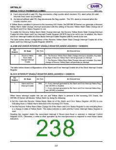
The table below shows configurations of the Receive Bipolar Violation Interrupt Enable bit of the Alarm and
Error Interrupt Enable Register (AEIER).
ALARM AND ERROR INTERRUPT ENABLE REGISTER (AEIER) (ADDRESS = 0X0B03H)
B
IT
B
IT
N
AME
B
IT
TYPE
BIT DESCRIPTION
N
UMBER
3
Receive Bipolar
Violation Interrupt
Enable
R/W
0 - The Receive Bipolar Violation interrupt is disabled. Occurrence of one
or more bipolar violations will not generate an interrupt.
1 - The Receive Bipolar Violation interrupt is enabled. Occurrence of one
or more bipolar violations will generate an interrupt.
228

 EXAR [ EXAR CORPORATION ]