XRT86L30
REV. 1.0.1
SINGLE T1/E1/J1 FRAMER/LIU COMBO
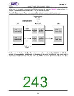
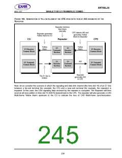
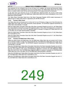
FIGURE 100. GENERATION OF
YELLOW ALARM BY THE CPE UPON DETECTION OF AIS ORIGINATED BY THE
R
EPEATER
Repeater declares
Red Alarm
internally
CPE detects AIS and
generates Yellow
Alarm to Repeater
Repeater generates
Yellow Alarm to CO
CO
Repeater
CPE
Yellow
Alarm
Yellow
Alarm
E1
Transmit
Section
E1
Receive
Section
E1 Receive
Framer Block
E1 Receive
Framer Block
AIS
E1
Receive
Section
E1
Transmit
Section
E1 Transmit
Framer Block
E1 Transmit
Framer Block
Repeater
generates AIS
to CPE
The E1 line is
broken
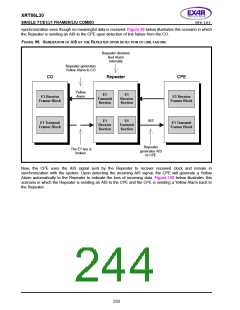
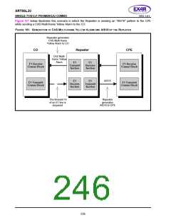
Next, let us consider the scenario in which the signaling and data link channel (the time slot 16) of an E1 line
between a far-end terminal (for example, the CO) and a near-end terminal (for example, the repeater) is
impaired. In this case, the CAS signaling data received by the repeater is corrupted. The Repeater will then
send an all ones pattern in time slot 16 (AIS16) downstream to the CPE. The repeater will also generate a CAS
Multi-frame Yellow Alarm upstream to the CO to indicate the loss of CAS Multi-frame synchronization.
234

 EXAR [ EXAR CORPORATION ]