áç
ST16C650A
2.90V TO 5.5V UART WITH 32-BYTE FIFO
REV. 5.0.0
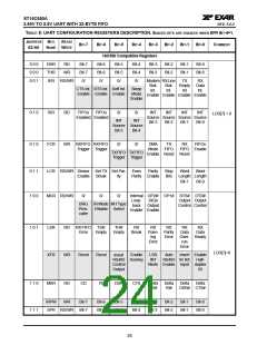
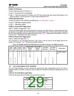
TABLE 8: UART CONFIGURATION REGISTERS DESCRIPTION. SHADED BITS ARE ENABLED WHEN EFR BIT-4=1.
ADDRESS
REG
READ/
WRITE
BIT-7
BIT-6
BIT-5
BIT-4
BIT-3
BIT-2
BIT-1
BIT-0
COMMENT
A2-A0
NAME
Baud Rate Generator Divisor
0 0 0
0 0 1
0 0 0
0 0 1
DLL RD/WR
DLM RD/WR
Bit-7
Bit-7
Bit-7
0
Bit-6
Bit-6
Bit-6
0
Bit-5
Bit-5
Bit-5
0
Bit-4
Bit-4
Bit-4
0
Bit-3
Bit-3
Bit-3
0
Bit-2
Bit-2
Bit-2
1
Bit-1
Bit-1
Bit-1
0
Bit-0
Bit-0
Bit-0
0
LCR[7]=1
≠
LCR 0xBF
DREV
DVID
RD
RD
LCR[7] = 1
≠
LCR 0xBF
DLL=0x00
DLM=0x00
Enhanced Registers
Enable
0 1 0
EFR
R/W
Auto
CTS
Enable Enable
Auto
RTS
Special
Char
Select
Soft-
ware
Flow
Cntl
Soft-
ware
Flow
Cntl
Soft-
ware
Flow
Cntl
Soft-
ware
Flow
Cntl
IER [7:4],
ISR [5:4],
FCR[5:4],
MCR[7:5]
MSR[7:4]
IRPW[7:0]
XFR[7:0]
Bit-3
Bit-2
Bit-1
Bit-0
LCR=0xBF
1 0 0
1 0 1
1 1 0
1 1 1
XON1
XON2
R/W
R/W
Bit-7
Bit-7
Bit-7
Bit-7
Bit-6
Bit-6
Bit-6
Bit-6
Bit-5
Bit-5
Bit-5
Bit-5
Bit-4
Bit-4
Bit-4
Bit-4
Bit-3
Bit-3
Bit-3
Bit-3
Bit-2
Bit-2
Bit-2
Bit-2
Bit-1
Bit-1
Bit-1
Bit-1
Bit-0
Bit-0
Bit-0
Bit-0
XOFF1 R/W
XOFF2 R/W
4.0 INTERNAL REGISTER DESCRIPTIONS
4.1 Receive Holding Register (RHR) - Read-Only
See “Receiver” on page 16.
4.2
Transmit Holding Register (THR) - Write-Only
See “Transmitter” on page 14.
4.3
Interrupt Enable Register (IER) - Read/Write
The Interrupt Enable Register (IER) masks the interrupts from receive data ready, transmit empty, line status
and modem status registers. These interrupts are reported in the Interrupt Status Register (ISR) register.
4.3.1
IER versus Receive FIFO Interrupt Mode Operation
When the receive FIFO (FCR bit-0 = a logic 1) and receive interrupts (IER bit-0 = logic 1) are enabled, the RHR
interrupts (see ISR bits 2 and 3) status will reflect the following:
A.
B.
C.
The receive data available interrupts are issued to the host when the FIFO has reached the programmed
trigger level. It will be cleared when the FIFO drops below the programmed trigger level.
FIFO level will be reflected in the ISR register when the FIFO trigger level is reached. Both the ISR register
status bit and the interrupt will be cleared when the FIFO drops below the trigger level.
The receive data ready bit (LSR bit-0) is set as soon as a character is transferred from the shift register to
the receive FIFO. It is reset when the FIFO is empty.
25

 EXAR [ EXAR CORPORATION ]