Document No.: FT_000288
FT232H SINGLE CHANNEL HI-SPEED USB TO MULTIPURPOSE UART/FIFO IC
Datasheet Version 1.8
Clearance No.: FTDI #199
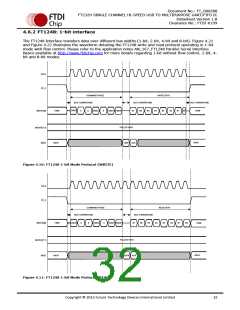
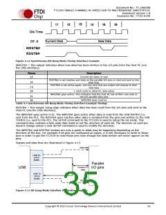
4.6.1 Bus Width Protocol Decode
In order for the FT1248 master to determine the bus width within the command phase the bus width is
encoded along with the actual commands on the first active clock edge when SS_n is active and has a
data width of 8-bits.
If any of the MIOSIO [7:4] signals are low then the data transfer width equals 8-bits
If any of the MIOSIO [3:2] signals are low then the data transfer width equals 4-bits
If MIOSIO [1] signal is low then the data transfer width equals 2-bits
Else the bus width is defaulted to 1-bit
Please note that if both of the MIOSIO bit signals are low then the data transfer width is equal to the
width of high priority MIOSIO bit signal. For example if both of the MIOSIO [7:3] signals are low then
the data transfer width equals 8-bits or if both of the MIOSIO [3:1] signals are low then the data transfer
width equals 4-bits
In order to successfully decode the bus width, all MIOSIO signals must have pull up resistors. By default,
all MIOSIO signals shall be seen by the FT232H in FT1248 mode as logic ‘1’. This means that when a
FT1248 master does not wish to use certain MIOSIO signals the slave (FT232H) is still capable of
determining the requested bus width since any unused MIOSIO signals shall be pull up in the slave.
The remaining bits used during the command phase are used to contain the command itself which means
that it is possible to define up to 16 unique commands.
LSB
CMD[3]
0
MSB
BWID 2-bit BWID 4-bit
CMD[2]
3
BWID 8-bit
4
CMD[1]
5
CMD[0]
6
X
7
1
2
1-bit Bus
Width
CMD[3]
0
X
1
X
2
CMD[2]
3
X
4
CMD[1]
5
CMD[0]
6
X
7
2-bit Bus
Width
CMD[3]
0
0
1
X
2
CMD[2]
3
X
4
CMD[1]
5
CMD[0]
6
X
7
4-bit Bus
Width
CMD[3]
0
X
1
0
2
CMD[2]
3
X
4
CMD[1]
5
CMD[0]
6
X
7
8-bit Bus
Width
CMD[3]
0
X
1
X
2
CMD[2]
3
0
4
CMD[1]
5
CMD[0]
6
X
7
Figure 4.9: FT1248 Command Structure
For more details about FT1248 Interface, please refer to application note AN_167_FT1248 Parallel Serial
Interface Basics available at http://www.ftdichip.com.
Copyright © 2012 Future Technology Devices International Limited
31

 ETC [ ETC ]