Document No.: FT_000288
FT232H SINGLE CHANNEL HI-SPEED USB TO MULTIPURPOSE UART/FIFO IC
Datasheet Version 1.8
Clearance No.: FTDI #199
Name
t1
t2
t3
t4
t5
t6
t7
t8
Min
Nom
16.67
8.33
Max Units
Comments
CLKOUT period
CLKOUT high period
CLKOUT low period
CLKOUT to RXF#
ns
7.5
7.5
0
0
0
7.5
0
7.5
0
0
7.5
0
9.17
9.17
9
9
9
ns
ns
ns
ns
ns
ns
ns
ns
ns
ns
ns
ns
ns
8.33
CLKOUT to read DATA valid
OE# to read DATA valid
OE# setup time
16.67
OE# hold time
RD# setup time to CLKOUT (RD# low after OE# low)
RD# hold time
t9
16.67
t10
t11
t12
t13
t14
t15
9
CLKOUT TO TXE#
16.67
Write DATA setup time
Write DATA hold time
WR# setup time to CLKOUT (WR# low after TXE# low)
WR# hold time
7.5
0
16.67
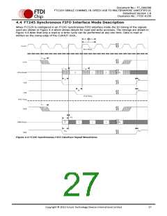
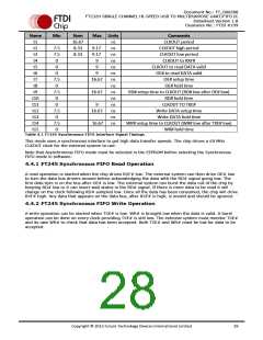
Table 4.1 FT245 Synchronous FIFO Interface Signal Timings
This mode uses a synchronous interface to get high data transfer speeds. The chip drives a 60 MHz
CLKOUT clock for the external system to use.
Note that Asynchronous FIFO mode must be selected in the EEPROM before selecting the Synchronous
FIFO mode in software.
4.4.1 FT245 Synchronous FIFO Read Operation
A read operation is started when the chip drives RXF# low. The external system can then drive OE# low
to turn the data bus drivers around before acknowledging the data with the RD# signal going low. The
first data byte is on the bus after OE# is low. The external system can burst the data out of the chip by
keeping RD# low or it can insert wait states in the RD# signal. If there is more data to be read it will
change on the clock following RD# sampled low. Once all the data has been consumed, the chip will drive
RXF# high. Any data that appears on the data bus, after RXF# is high, is invalid and should be ignored.
4.4.2 FT245 Synchronous FIFO Write Operation
A write operation can be started when TXE# is low. WR# is brought low when the data is valid. A burst
operation can be done on every clock providing TXE# is still low. The external system must monitor TXE#
and its own WR# to check that data has been accepted. Both TXE# and WR# must be low for data to be
accepted.
Copyright © 2012 Future Technology Devices International Limited
28

 ETC [ ETC ]