Epson Research and Development
Page 149
Vancouver Design Center
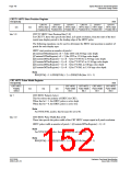
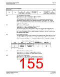
CRT/TV Output Control Register
REG[05Bh]
RW
TV
Chrominance
Filter Enable Filter Enable
TV
Luminance
TV S-Video/
Composite
Output Select Output Select
TV
PAL/NTSC
DAC Output
Level Select
n/a
n/a
n/a
bit 5
bit 4
bit 3
TV Chrominance Filter Enable
When this bit = 1, the TV chrominance filter is enabled.
When this bit = 0, there is no hardware effect.
The chrominance filter adjusts the color of the TV by limiting the bandwidth of the
chrominance signal (reducing cross-luminance distortion). This reduces the “ragged
edges” seen at boundaries between sharp color transitions. This filter is most useful for
composite video output.
TV Luminance Filter Enable
When this bit = 1, the TV luminance filter is enabled.
When this bit = 0, there is no hardware effect.
The luminance filter adjusts the brightness of the TV by limiting the bandwidth of the
luminance signal (reducing cross-chrominance distortion). This reduces the “rainbow-
like” colors at boundaries between sharp luminance transitions. This filter is most useful
for composite video output.
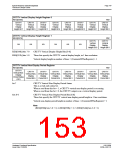
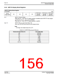
DAC Output Level Select
This bit should be set based on the conditions in the following table. When this bit is set to
1 it allows IREF to be reduced. For an example implementation of the required external
CRT/TV circuitry, see Figure 5-2: “External Circuitry for CRT/TV Interface,” on page 44.
Table 8-22: DAC Output Level Selection
LCD
CRT
TV
REG[05Bh] bit 3
IREF (mA)
Supported
Not Supported
Supported
Supported
Not Supported
Not Supported
Supported
x
1
0
x
x
x
4.6
9.2
x
= don’t care
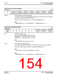
bit 1
bit 0
TV S-Video/Composite Output Select
When this bit = 1, S-Video TV signal output is selected.
When this bit = 0, Composite TV signal output is selected.
TV PAL/NTSC Output Select
When this bit = 1, PAL format TV signal output is selected.
When this bit = 0, NTSC format TV signal output is selected.
This bit must be set to 0 when CRT mode is enabled.
Hardware Functional Specification
Issue Date: 01/02/06
S1D13506
X25B-A-001-10

 EPSON [ EPSON COMPANY ]