Epson Research and Development
Page 153
Vancouver Design Center
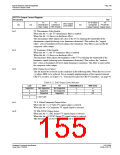
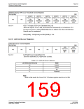
CRT/TV Display FIFO Low Threshold Control Register
REG[06Bh]
RW
CRT/TV
CRT/TV
CRT/TV
CRT/TV
CRT/TV
CRT/TV
Display FIFO Display FIFO Display FIFO Display FIFO Display FIFO Display FIFO
n/a
n/a
Low
Threshold
Bit 5
Low
Threshold
Bit 4
Low
Threshold
Bit 3
Low
Threshold
Bit 2
Low
Threshold
Bit 1
Low
Threshold
Bit 0
bits 5-0
CRT/TV Display FIFO Low Threshold Bits [5:0]
When this register is set to 00h, the threshold is automatically set in hardware. If it
becomes necessary to adjust REG[04Ah] from its default value, then the following
formula must be maintained:
REG[04Bh] > REG[04Ah] and REG[04Bh] ≤ 3Ch
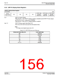
8.3.10 LCD Ink/Cursor Registers
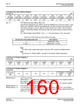
LCD Ink/Cursor Control Register
REG[070h]
RW
LCD
Ink/Cursor
Mode
LCD
Ink/Cursor
Mode
n/a
n/a
n/a
n/a
n/a
n/a
Bit 1
Bit 0
bits 1-0
LCD Ink/Cursor Control Bits [1:0]
These bits enable the LCD Ink/Cursor circuitry.
Table 8-25: LCD Ink/Cursor Selection
LCD Ink/Cursor Bits [1:0]
Mode
Inactive
Cursor
Ink
00
01
10
11
Reserved
Note
While in Ink mode, the Cursor X & Y Position registers must be set to 00h.
Hardware Functional Specification
Issue Date: 01/02/06
S1D13506
X25B-A-001-10

 EPSON [ EPSON COMPANY ]