DA14580
FINAL
Bluetooth Low Energy 4.2 SoC
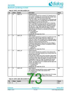
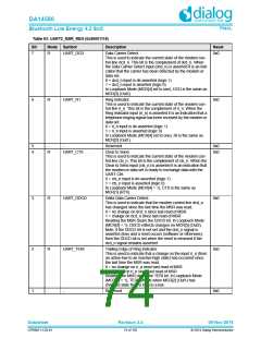
Table 93: UART2_MSR_REG (0x50001118)
Bit
Mode Symbol
R UART_DCD
Description
Reset
0x0
7
Data Carrier Detect.
This is used to indicate the current state of the modem con-
trol line dcd_n. This bit is the complement of dcd_n. When
the Data Carrier Detect input (dcd_n) is asserted it is an indi-
cation that the carrier has been detected by the modem or
data set.
0 = dcd_n input is de-asserted (logic 1)
1 = dcd_n input is asserted (logic 0)
In Loopback Mode (MCR[4] set to one), DCD is the same as
MCR[3] (Out2).
6
R
UART_R1
Ring Indicator.
0x0
This is used to indicate the current state of the modem con-
trol line ri_n. This bit is the complement of ri_n. When the
Ring Indicator input (ri_n) is asserted it is an indication that a
telephone ringing signal has been received by the modem or
data set.
0 = ri_n input is de-asserted (logic 1)
1 = ri_n input is asserted (logic 0)
In Loopback Mode (MCR[4] set to one), RI is the same as
MCR[2] (Out1).
5
4
-
-
Reserved
0x0
0x0
R
UART_CTS
Clear to Send.
This is used to indicate the current state of the modem con-
trol line cts_n. This bit is the complement of cts_n. When the
Clear to Send input (cts_n) is asserted it is an indication that
the modem or data set is ready to exchange data with the
UART Ctrl.
0 = cts_n input is de-asserted (logic 1)
1 = cts_n input is asserted (logic 0)
In Loopback Mode (MCR[4] = 1), CTS is the same as
MCR[1] (RTS).
3
R
UART_DDCD
Delta Data Carrier Detect.
0x0
This is used to indicate that the modem control line dcd_n
has changed since the last time the MSR was read.
0 = no change on dcd_n since last read of MSR
1 = change on dcd_n since last read of MSR
Reading the MSR clears the DDCD bit. In Loopback Mode
(MCR[4] = 1), DDCD reflects changes on MCR[3] (Out2).
Note, if the DDCD bit is not set and the dcd_n signal is
asserted (low) and a reset occurs (software or otherwise),
then the DDCD bit is set when the reset is removed if the
dcd_n signal remains asserted.
2
R
UART_TERI
Trailing Edge of Ring Indicator.
0x0
This is used to indicate that a change on the input ri_n (from
an active-low to an inactive-high state) has occurred since
the last time the MSR was read.
0 = no change on ri_n since last read of MSR
1 = change on ri_n since last read of MSR
Reading the MSR clears the TERI bit. In Loopback Mode
(MCR[4] = 1), TERI reflects when MCR[2] (Out1) has
changed state from a high to a low.
1
-
-
Reserved
0x0
Datasheet
Revision 3.4
09-Nov-2016
CFR0011-120-01
74 of 155
© 2014 Dialog Semiconductor

 DIALOG [ Dialog Semiconductor ]