DA14580
FINAL
Bluetooth Low Energy 4.2 SoC
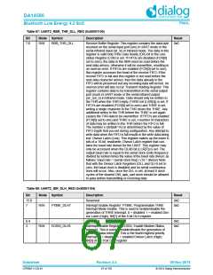
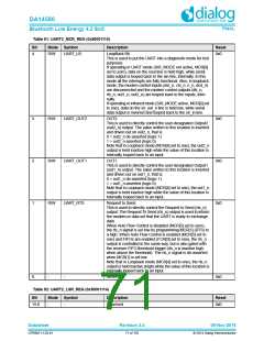
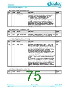
Table 91: UART2_MCR_REG (0x50001110)
Bit
Mode Symbol
Description
Reset
4
R/W
UART_LB
LoopBack Bit.
0x0
This is used to put the UART into a diagnostic mode for test
purposes.
If operating in UART mode (SIR_MODE not active, MCR[6]
set to zero), data on the sout line is held high, while serial
data output is looped back to the sin line, internally. In this
mode all the interrupts are fully functional. Also, in loopback
mode, the modem control inputs (dsr_n, cts_n, ri_n, dcd_n)
are disconnected and the modem control outputs (dtr_n,
rts_n, out1_n, out2_n) are looped back to the inputs, inter-
nally.
If operating in infrared mode (SIR_MODE active, MCR[6] set
to one), data on the sir_out_n line is held low, while serial
data output is inverted and looped back to the sir_in line.
3
2
1
R/W
R/W
R/W
UART_OUT2
UART_OUT1
UART_RTS
OUT2.
0x0
0x0
0x0
This is used to directly control the user-designated Output2
(out2_n) output. The value written to this location is inverted
and driven out on out2_n, that is:
0 = out2_n de-asserted (logic 1)
1 = out2_n asserted (logic 0)
Note that in Loopback mode (MCR[4] set to one), the out2_n
output is held inactive high while the value of this location is
internally looped back to an input.
OUT1.
This is used to directly control the user-designated Output1
(out1_n) output. The value written to this location is inverted
and driven out on out1_n, that is:
0 = out1_n de-asserted (logic 1)
1 = out1_n asserted (logic 0)
Note that in Loopback mode (MCR[4] set to one), the out1_n
output is held inactive high while the value of this location is
internally looped back to an input.
Request to Send.
This is used to directly control the Request to Send (rts_n)
output. The Request To Send (rts_n) output is used to inform
the modem or data set that the UART is ready to exchange
data.
When Auto Flow Control is disabled (MCR[5] set to zero),
the rts_n signal is set low by programming MCR[1] (RTS) to
a high. When Auto Flow Control is enabled (MCR[5] set to
one) and FIFOs are enabled (FCR[0] set to one), the rts_n
output is controlled in the same way, but is also gated with
the receiver FIFO threshold trigger (rts_n is inactive high
when above the threshold). The rts_n signal is de-asserted
when MCR[1] is set low.
Note that in Loopback mode (MCR[4] set to one), the rts_n
output is held inactive (high) while the value of this location is
internally looped back to an input.
0
-
-
Reserved
0x0
Table 92: UART2_LSR_REG (0x50001114)
Bit
Mode Symbol
Description
Reset
15:8
-
-
Reserved
0x0
Datasheet
Revision 3.4
09-Nov-2016
CFR0011-120-01
71 of 155
© 2014 Dialog Semiconductor

 DIALOG [ Dialog Semiconductor ]