DA14580
FINAL
Bluetooth Low Energy 4.2 SoC
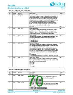
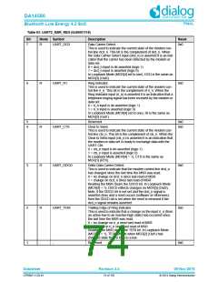
Table 90: UART2_LCR_REG (0x5000110C)
Bit
Mode Symbol
Description
Reset
6
R/W
UART_BC
Break Control Bit.
0x0
This is used to cause a break condition to be transmitted to
the receiving device. If set to one the serial output is forced
to the spacing (logic 0) state. When not in Loopback Mode,
as determined by MCR[4], the sout line is forced low until the
Break bit is cleared. If active (MCR[6] set to one) the
sir_out_n line is continuously pulsed. When in Loopback
Mode, the break condition is internally looped back to the
receiver and the sir_out_n line is forced low.
5
4
-
-
Reserved
0x0
0x0
R/W
UART_EPS
Even Parity Select.
This is used to select between even and odd parity, when
parity is enabled (PEN set to one). If set to one, an even
number of logic 1s is transmitted or checked. If set to zero,
an odd number of logic 1s is transmitted or checked.
3
2
R/W
R/W
UART_PEN
Parity Enable.
0x0
0x0
This bit is used to enable and disable parity generation and
detection in transmitted and received serial character
respectively.
0 = parity disabled
1 = parity enabled
UART_STOP
Number of stop bits.
This is used to select the number of stop bits per character
that the peripheral transmits and receives. If set to zero, one
stop bit is transmitted in the serial data.
If set to one and the data bits are set to 5 (LCR[1:0] set to
zero) one and a half stop bits is transmitted. Otherwise, two
stop bits are transmitted. Note that regardless of the number
of stop bits selected, the receiver checks only the first stop
bit.
0 = 1 stop bit
1 = 1.5 stop bits when DLS (LCR[1:0]) is zero, else 2 stop bit
1:0
R/W
UART_DLS
Data Length Select.
0x0
This is used to select the number of data bits per character
that the peripheral transmits and receives. The number of bit
that may be selected areas follows:
00 = 5 bits
01 = 6 bits
10 = 7 bits
11 = 8 bits
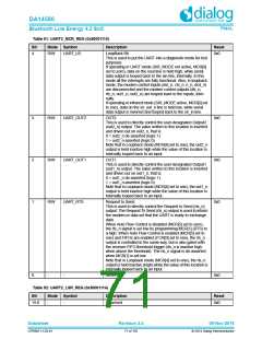
Table 91: UART2_MCR_REG (0x50001110)
Bit
15:7
6
Mode Symbol
Description
Reset
0x0
-
-
Reserved
R/W
UART_SIRE
SIR Mode Enable.
0x0
This is used to enable/disable the IrDA SIR Mode features
as described in "IrDA 1.0 SIR Protocol" on page 53.
0 = IrDA SIR Mode disabled
1 = IrDA SIR Mode enabled
5
R/W
UART_AFCE
Auto Flow Control Enable.
0x0
When FIFOs are enabled and the Auto Flow Control Enable
(AFCE) bit is set, hardware Auto Flow Control is enabled via
CTS and RTS.
0 = Auto Flow Control Mode disabled
1 = Auto Flow Control Mode enabled
Datasheet
Revision 3.4
09-Nov-2016
CFR0011-120-01
70 of 155
© 2014 Dialog Semiconductor

 DIALOG [ Dialog Semiconductor ]