DA14580
FINAL
Bluetooth Low Energy 4.2 SoC
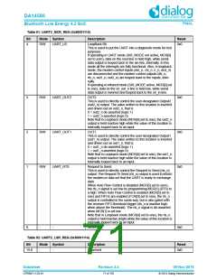
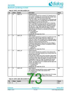
Table 93: UART2_MSR_REG (0x50001118)
Bit
Mode Symbol
UART_DCTS
Description
Reset
0
R
Delta Clear to Send.
0x0
This is used to indicate that the modem control line cts_n
has changed since the last time the MSR was read.
0 = no change on cts_n since last read of MSR
1 = change on cts_n since last read of MSR
Reading the MSR clears the DCTS bit. In Loopback Mode
(MCR[4] = 1), DCTS reflects changes on MCR[1] (RTS).
Note, if the DCTS bit is not set and the cts_n signal is
asserted (low) and a reset occurs (software or otherwise),
then the DCTS bit is set when the reset is removed if the
cts_n signal remains asserted.
Table 94: UART2_SCR_REG (0x5000111C)
Bit
Mode Symbol
Description
Reset
0x0
15:8
7:0
-
-
Reserved
R/W
UART_SCRATCH_P
AD
This register is for programmers to use as a temporary stor-
age space. It has no defined purpose in the UART Ctrl.
0x0
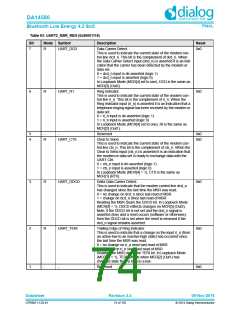
Table 95: UART2_LPDLL_REG (0x50001120)
Bit
Mode Symbol
Description
Reset
0x0
15:8
7:0
-
-
Reserved
R/W
UART_LPDLL
This register makes up the lower 8-bits of a 16-bit, read/
write, Low Power Divisor Latch register that contains the
baud rate divisor for the UART, which must give a baud rate
of 115.2K. This is required for SIR Low Power (minimum
pulse width) detection at the receiver. This register may be
accessed only when the DLAB bit (LCR[7]) is set.
The output low-power baud rate is equal to the serial clock
(sclk) frequency divided by sixteen times the value of the
baud rate divisor, as follows:
0x0
Low power baud rate = (serial clock frequency)/(16* divisor)
Therefore, a divisor must be selected to give a baud rate of
115.2K.
NOTE: When the Low Power Divisor Latch registers (LPDLL
and LPDLH) are set to 0, the low-power baud clock is dis-
abled and no low-power pulse detection (or any pulse detec-
tion) occurs at the receiver. Also, once the LPDLL is set, at
least eight clock cycles of the slowest UART Ctrl clock
should be allowed to pass before transmitting or receiving
data.
Table 96: UART2_LPDLH_REG (0x50001124)
Bit
Mode Symbol
Description
Reset
15:8
-
-
Reserved
0x0
Datasheet
Revision 3.4
09-Nov-2016
CFR0011-120-01
75 of 155
© 2014 Dialog Semiconductor

 DIALOG [ Dialog Semiconductor ]