DA14580
FINAL
Bluetooth Low Energy 4.2 SoC
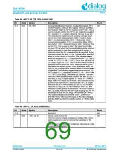
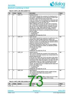
Table 89: UART2_IIR_FCR_REG (0x50001108)
Bit
Mode Symbol
R/W IIR_FCR
Description
Reset
15:0
Interrupt Identification Register, reading this register; FIFO
Control Register, writing to this register. Interrupt Identifica-
tion Register: Bits[7:6], FIFO's Enabled (or FIFOSE): This is
used to indicate whether the FIFO's are enabled or disabled.
00 = disabled. 11 = enabled. Bits[3:0], Interrupt ID (or IID):
This indicates the highest priority pending interrupt which
can be one of the following types: 0000 = modem status.
0001 = no interrupt pending. 0010 = THR empty. 0100 =
received data available. 0110 = receiver line status. 0111 =
busy detect. 1100 = character timeout. Bits[7:6], RCVR Trig-
ger (or RT):. This is used to select the trigger level in the
receiver FIFO at which the Received Data Available Interrupt
will be generated. In auto flow control mode it is used to
determine when the rts_n signal will be de-asserted. It also
determines when the dma_rx_req_n signal will be asserted
when in certain modes of operation. The following trigger
levels are supported: 00 = 1 character in the FIFO 01 = FIFO
1/4 full 10 = FIFO 1/2 full 11 = FIFO 2 less than full Bits[5:4],
TX Empty Trigger (or TET): This is used to select the empty
threshold level at which the THRE Interrupts will be gener-
ated when the mode is active. It also determines when the
dma_tx_req_n signal will be asserted when in certain modes
of operation. The following trigger levels are supported: 00 =
FIFO empty 01 = 2 characters in the FIFO 10 = FIFO 1/4 full
11 = FIFO 1/2 full Bit[3], DMA Mode (or DMAM): This deter-
mines the DMA signalling mode used for the dma_tx_req_n
and dma_rx_req_n output signals. 0 = mode 0 1 = mode 1
Bit[2], XMIT FIFO Reset (or XFIFOR): This resets the control
portion of the transmit FIFO and treats the FIFO as empty.
Note that this bit is 'self-clearing' and it is not necessary to
clear this bit. Bit[1], RCVR FIFO Reset (or RFIFOR): This
resets the control portion of the receive FIFO and treats the
FIFO as empty. Note that this bit is 'self-clearing' and it is not
necessary to clear this bit. Bit[0], FIFO Enable (or FIFOE):
This enables/disables the transmit (XMIT) and receive
(RCVR) FIFO's. Whenever the value of this bit is changed
both the XMIT and RCVR controller portion of FIFO's will be
reset.
0x0
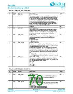
Table 90: UART2_LCR_REG (0x5000110C)
Bit
15:8
7
Mode Symbol
Description
Reset
0x0
-
-
Reserved
R/W
UART_DLAB
Divisor Latch Access Bit.
0x0
This bit is used to enable reading and writing of the Divisor
Latch register (DLL and DLH) to set the baud rate of the
UART.
This bit must be cleared after initial baud rate setup in order
to access other registers.
Datasheet
Revision 3.4
09-Nov-2016
CFR0011-120-01
69 of 155
© 2014 Dialog Semiconductor

 DIALOG [ Dialog Semiconductor ]