DA14580
FINAL
Bluetooth Low Energy 4.2 SoC
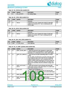
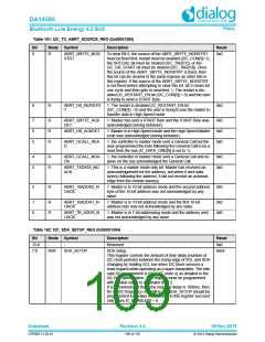
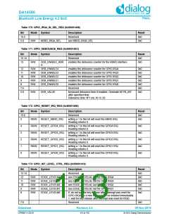
Table 161: I2C_TX_ABRT_SOURCE_REG (0x50001380)
Bit
Mode Symbol
R ABRT_SBYTE_NOR
Description
Reset
0x0
9
To clear Bit 9, the source of the ABRT_SBYTE_NORSTRT
must be fixed first; restart must be enabled (I2C_CON[5]=1),
the SPECIAL bit must be cleared (I2C_TAR[11]), or the
GC_OR_START bit must be cleared (I2C_TAR[10]). Once
the source of the ABRT_SBYTE_NORSTRT is fixed, then
this bit can be cleared in the same manner as other bits in
this register. If the source of the ABRT_SBYTE_NORSTRT
is not fixed before attempting to clear this bit, bit 9 clears for
one cycle and then gets re-asserted. 1: The restart is dis-
abled (IC_RESTART_EN bit (I2C_CON[5]) = 0) and the user
is trying to send a START Byte.
STRT
8
R
ABRT_HS_NORSTR
T
1: The restart is disabled (IC_RESTART_EN bit
(I2C_CON[5]) = 0) and the user is trying to use the master to
transfer data in High Speed mode
0x0
7
6
5
R
R
R
ABRT_SBYTE_ACK
DET
1: Master has sent a START Byte and the START Byte was
acknowledged (wrong behavior).
0x0
0x0
0x0
ABRT_HS_ACKDET
1: Master is in High Speed mode and the High Speed Master
code was acknowledged (wrong behavior).
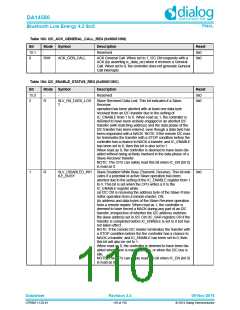
ABRT_GCALL_REA
D
1: the controller in master mode sent a General Call but the
user programmed the byte following the General Call to be a
read from the bus (IC_DATA_CMD[9] is set to 1).
4
3
R
R
ABRT_GCALL_NOA
CK
1: the controller in master mode sent a General Call and no
slave on the bus acknowledged the General Call.
0x0
0x0
ABRT_TXDATA_NO
ACK
1: This is a master-mode only bit. Master has received an
acknowledgement for the address, but when it sent data
byte(s) following the address, it did not receive an acknowl-
edge from the remote slave(s).
2
R
ABRT_10ADDR2_N
OACK
1: Master is in 10-bit address mode and the second address
byte of the 10-bit address was not acknowledged by any
slave.
0x0
1
0
R
R
ABRT_10ADDR1_N
OACK
1: Master is in 10-bit address mode and the first 10-bit
address byte was not acknowledged by any slave.
0x0
0x0
ABRT_7B_ADDR_N
OACK
1: Master is in 7-bit addressing mode and the address sent
was not acknowledged by any slave.
Table 162: I2C_SDA_SETUP_REG (0x50001394)
Bit
Mode Symbol
Description
Reset
0x0
15:8
7:0
-
-
Reserved
R/W
SDA_SETUP
SDA Setup.
0x64
This register controls the amount of time delay (number of
I2C clock periods) between the rising edge of SCL and SDA
changing by holding SCL low when I2C block services a
read request while operating as a slave-transmitter. The rele-
vant I2C requirement is tSU:DAT (note 4) as detailed in the
I2C Bus Specification. This register must be programmed
with a value equal to or greater than 2.
It is recommended that if the required delay is 1000ns, then
for an I2C frequency of 10 MHz, IC_SDA_SETUP should be
programmed to a value of 11.Writes to this register succeed
only when IC_ENABLE[0] = 0.
Datasheet
Revision 3.4
09-Nov-2016
CFR0011-120-01
109 of 155
© 2014 Dialog Semiconductor

 DIALOG [ Dialog Semiconductor ]