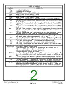
Data Format:
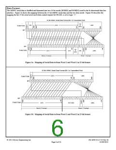
The ARINC serial data is shuffled and formatted into two 16 bit words (WORD1 and WORD2) used by the bi-directional data bus
interface. Figure 3a shows the mapping between the 32 bit ARINC serial data and the two data words. Figure 3b describes the
mapping for the 25 bit serial word used when control register bit WLSEL is set to logic “1”.
32 Bit ARINC Serial Data Format (Bit 1 is Transmitted First)
S/D
SSM
DATA
or
LABEL
FUNCTION
BIT
DATA
32 31 30 29 28 27 26 25 24 23 22 21 20 19 18 17 16 15 14 13 12 11 10
9
8
7
6
5
4
3
2
1
15 14 13 12 11 10
9
8
7
6
5
4
3
2
1
0
15 14 13 12 11 10
S/D
9
8
7
6
5
4
3
2
1
0
BIT
FUNCTION
DATA
DATA
or
SSM
LABEL
DATA
Word 2 Format
Word 1 Format
Figure 3a: Mapping of Serial Data to/from Word 1 and Word 2 in 32 bit format.
25 Bit ARINC Serial Data Format (Bit 1 is Transmitted First)
DATA
LABEL
FUNCTION
BIT
25 24 23 22 21 20 19 18 17 16 15 14 13 12 11 10
9
8
7
6
5
4
3
2
1
15 14 13 12 11 10
9
8
7
6
5
4
3
2
1
0
15 14 13 12 11 10
NOT USED
9
8
7
6
5
4
3
2
1
0
BIT
FUNCTION
DATA
LABEL
Word 2 Format
Word 1 Format
Figure 3b: Mapping of Serial Data to/from Word 1 and Word 2 in 25 bit format.
© 2012 Device Engineering Inc.
DS-MW-01117-01 Rev B
02/09/2012
Page 6 of 14

 DEIAZ [ Device Engineering Incorporated ]