DS3251/DS3252/DS3253/DS3254
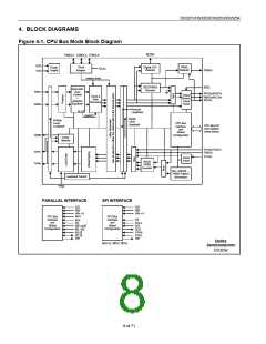
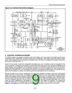
Figure 4-2. Hardware Mode Block Diagram
RMONn T3MCLK E3MCLK STMCLK
RJAn
RLOSn
RBIN
VDD
VSS
Power
Supply
Clock
Digital LOS
Detector
PRBS
TCLKn
Adapter
Detector
PRBSn
master clock
B3ZS/HDB3
Decoder
RTSn
Automatic
Gain
RXPn
RXNn
RPOSn/RDATn
RNEGn/RLCVn
RCLKn
Control
+
Output
Drivers,
Clock
Clock &
Data
Adaptive
Equalizer
Recovery
Invert
RCINV
Remote
ALOS
Loopback
squelch
Digital
Analog
Local
HIZ
RST
Local
Loopback
Loopback
Global
HW
Configuration
E3Mn
STSn
TDMn
Driver
Monitor
TPOSn/TDATn
TNEGn
TXPn
TXNn
TCLKn
Clock
Invert
B3ZS/
HDB3
TCINV
Encoder
AIS, 100100…,
PRBS Pattern
Generation
Loopback Control
TTSn LLBn RLBn
TLBOn
TJAn
TBIN
TDSAn,
TDSBn
Dallas
Semiconductor
DS325x
5. CONTROL INTERFACE MODES
The DS325x devices can operate in hardware mode or two different CPU bus modes: 8-bit parallel and SPI serial.
In hardware mode, configuration input pins control device configuration, while status output pins indicate device
status. Internal registers are not accessible in hardware mode. The device is configured for hardware mode when
the HW pin is wired high (HW = 1).
In the CPU bus modes, most of the configuration and status pins used in hardware mode are reassigned to the
CPU bus interface. Through the bus interface an external processor can access a set of internal configuration and
status registers. A few configuration and status pins are active in both hardware mode and the CPU bus modes to
support specialized applications, such as protection switching. The device is configured for CPU bus mode when
the HW pin is wired low (HW = 0). The default CPU interface is 8-bit parallel. When the MOT, RD and WR pins are
all low, the SPI interface is enabled. See Section 15 for more information on the CPU interfaces.
With the exception of the HW pin, configuration and status pins available in hardware mode have corresponding
register bits in the CPU bus mode. The hardware mode pins and the CPU bus mode register bits have identical
names and functions, with the exception that all register bits are active high. For example, LOS is indicated by the
receiver on the RLOS pin (active low) in hardware mode and the RLOS register bit (active high) in CPU bus mode.
The few configuration input pins that are active in CPU bus mode also have corresponding register bits. In these
cases, the actual configuration is the logical OR of pin assertion and register bit assertion. For example, the
transmitter output driver is tri-stated if the TTS pin is asserted (i.e., low) or the TTS register bit is asserted (high).
Figure 4-1 and Figure 4-2 show block diagrams of the DS325x in hardware mode and in CPU bus mode.
9 of 71

 DALLAS [ DALLAS SEMICONDUCTOR ]