DS2406
WRITING EPROM MEMORY
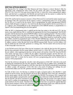
The function flow for writing to the Data Memory and Status Memory is almost identical. After the
appropriate write command has been issued, the bus master will send a two-byte starting address
(TA1=(T7:T0), TA2=(T15:T8)) and a byte of data (D7:D0). A 16-bit CRC of the command byte, address
bytes, and data byte is computed by the DS2406 and read back by the bus master to confirm that the
correct command word, starting address, and data byte were received.
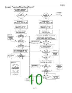
If the CRC read by the bus master is incorrect, a Reset Pulse must be issued and the entire sequence must
be repeated. If the CRC received by the bus master is correct, a programming pulse (12V on the 1-Wire
bus for 480 µs) is issued by the bus master. Prior to programming, the entire unprogrammed EPROM
memory field will appear as logical 1s. For each bit in the data byte provided by the bus master that is set
to a logical 0, the corresponding bit in the selected byte of the EPROM memory is programmed to a
logical 0 after the programming pulse has been applied.
After the 480 µs programming pulse is applied and the data line returns to the idle level (5V), the bus
master issues eight read time slots to verify that the appropriate bits have been programmed. The DS2406
responds with the data from the selected EPROM address sent least significant bit first. This byte contains
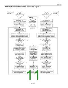
the bit-wise logical AND of all data ever written to this address. If the EPROM byte contains 1s in bit
positions where the byte issued by the master contained 0s, a Reset Pulse should be issued and the current
byte address should be programmed again. If the DS2406 EPROM byte contains 0s in the same bit
positions as the data byte, the programming was successful and the DS2406 will automatically increment
its address counter to select the next byte in the EPROM memory field. The new two-byte address will
also be loaded into the 16-bit CRC generator as a starting value. The bus master will issue the next byte
of data using eight write time slots.
As the DS2406 receives this byte of data into the scratchpad, it also shifts the data into the CRC generator
that has been preloaded with the current address and the result is a 16-bit CRC of the new data byte and
the new address. After supplying the data byte, the bus master will read this 16-bit CRC from the DS2406
with sixteen read time slots to confirm that the address incremented properly and the data byte was
received correctly. If the CRC is incorrect, a Reset Pulse must be issued and the write sequence must be
restarted. If the CRC is correct, the bus master will issue a programming pulse and the selected byte in
memory will be programmed.
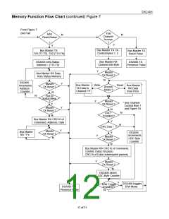
Note that the initial pass through the write flow chart will generate an 16-bit CRC value that is the result
of shifting the command byte into the CRC generator, followed by the two address bytes, and finally the
data byte. Subsequent passes through the write flow chart due to the DS2406 automatically incrementing
its address counter will generate a 16-bit CRC that is the result of loading (not shifting) the new
(incremented) address into the CRC generator and then shifting in the new data byte.
For both of these cases, the decision to continue (to apply a program pulse to the DS2406) is made
entirely by the bus master, since the DS2406 will not be able to determine if the 16-bit CRC calculated by
the bus master agrees with the 16-bit CRC calculated by the DS2406. If an incorrect CRC is ignored and
the bus master applies a program pulse, incorrect programming could occur within the DS2406. Also note
that the DS2406 will always increment its internal address counter after the receipt of the eight read time
slots used to confirm the programming of the selected EPROM byte. The decision to continue is again
made entirely by the bus master. Therefore if the EPROM data byte does not match the supplied data byte
but the master continues with the write command, incorrect programming could occur within the DS2406.
The write command sequence can be ended at any point by issuing a Reset Pulse.
9 of 31

 DALLAS [ DALLAS SEMICONDUCTOR ]