DS2406
Extended Read Memory [A5h]
The Extended Read Memory command supports page redirection when reading data from the 1024-bit
EPROM data field. One major difference between the Extended Read Memory and the basic Read
Memory command is that the bus master receives the Redirection Byte (see description of Status
Memory) first before investing time in reading data from the addressed memory location. This allows the
bus master to quickly decide whether to continue and access the data at the selected starting page or to
terminate and restart the reading process at the redirected page address.
In addition to page redirection, the Extended Read Memory command also supports “bit-oriented”
applications where the user cannot store a 16-bit CRC with the data itself. With bit-oriented applications
the EPROM information may change over time within a page boundary making it impossible to include
an accompanying CRC that will always be valid. Therefore, the Extended Read Memory command
concludes each page with the DS2406 generating and supplying a 16-bit CRC that is based on and
therefore always consistent with the current data stored in each page of the 1024-bit EPROM data field.
After having sent the command code of the Extended Read Memory command, the bus master sends a
two-byte address (TA1=(T7:T0), TA2=(T15:T8)) that indicates a starting byte location within the data
field. By sending eight read data time slots, the master receives the Redirection Byte associated with the
page given by the starting address. With the next sixteen read data time slots, the bus master receives a
16-bit CRC of the command byte, address bytes and the Redirection Byte. This CRC is computed by the
DS2406 and read back by the bus master to check if the command word, starting address and Redirection
Byte were received correctly.
If the CRC read by the bus master is incorrect, a Reset Pulse must be issued and the entire sequence must
be repeated. If the CRC received by the bus master is correct, the bus master issues read time slots and
receives data from the DS2406 starting at the initial address and continuing until the end of a 32-byte
page is reached. At that point the bus master will send sixteen additional read time slots and receive a 16-
bit CRC that is the result of shifting into the CRC generator all of the data bytes from the initial starting
byte to the last byte of the current page.
With the next 24 read data time slots the master will receive the Redirection Byte of the next page
followed by a 16-bit CRC of the Redirection Byte. After this, data is again read from the 1024-bits
EPROM data field starting at the beginning of the new page. This sequence will continue until the final
page and its accompanying CRC are read by the bus master.
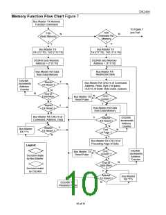
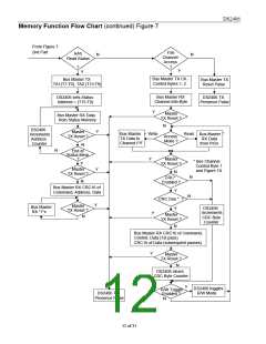
The Extended Read Memory command provides a 16-bit CRC at two locations within the transaction
flow chart: 1) after the Redirection Byte and 2) at the end of each memory page. The CRC at the end of
the memory page is always the result of clearing the CRC generator and shifting in the data bytes
beginning at the first addressed memory location of the EPROM data page until the last byte of this page.
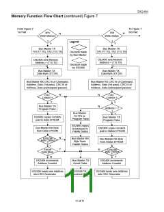
With the initial pass through the Extended Read Memory flow chart the 16-bit CRC value after the
Redirection Byte is the result of shifting the command byte into the cleared CRC generator, followed by
the two address bytes and the Redirection Byte. Subsequent passes through the Extended Read Memory
flow chart will generate a 16-bit CRC that is the result of clearing the CRC generator and then shifting in
the Redirection Byte only. After the 16-bit CRC of the last page is read, the bus master will receive
logical 1s from the DS2406 until a Reset Pulse is issued. The Extended Read Memory command
sequence can be ended at any point by issuing a Reset Pulse.
8 of 31

 DALLAS [ DALLAS SEMICONDUCTOR ]