DS2406
PARASITE POWER
The DS2406 can derive its power entirely from the 1-Wire bus by storing energy on an internal capacitor
during periods of time when the signal line is high. During low times the device continues to operate off
of this “parasite” power source until the 1-Wire bus returns high to replenish the parasite (capacitor)
supply. In applications where the device may be temporarily disconnected from the 1-Wire bus or where
the low-times of the 1-Wire bus may be very long the VCC pin may be connected to an external voltage
supply to maintain the device status.
When writing to the EPROM memory, the 1-Wire communication occurs at normal voltage levels and
then is pulsed momentarily to the programming voltage to cause the selected EPROM bits to be
programmed. The bus master must be able to provide 12V and 10mA to adequately program the EPROM
portions of the device. During programming, only EPROM-based devices are allowed to be present on
the 1-Wire bus.
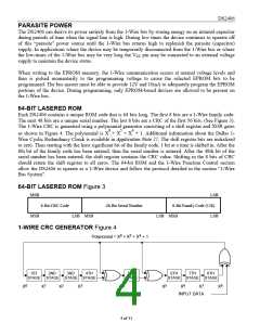
64-BIT LASERED ROM
Each DS2406 contains a unique ROM code that is 64 bits long. The first 8 bits are a 1-Wire family code.
The next 48 bits are a unique serial number. The last 8 bits are a CRC of the first 56 bits. (See Figure 3).
The 1-Wire CRC is generated using a polynomial generator consisting of a shift register and XOR gates
as shown in Figure 4. The polynomial is X8 + X5 + X4 + 1. Additional information about the Dallas 1-
Wire Cyclic Redundancy Check is available in Application Note 27. The shift register bits are initialized
to zero. Then starting with the least significant bit of the family code, 1 bit at a time is shifted in. After the
8th bit of the family code has been entered, then the serial number is entered. After the 48th bit of the
serial number has been entered, the shift register contains the CRC value. Shifting in the 8 bits of CRC
should return the shift register to all zeros. The 64-bit ROM and the 1-Wire Function Control section
allow the DS2406 to operate as a 1-Wire device and follow the protocol detailed in the section “1-Wire
Bus System”.
64-BIT LASERED ROM Figure 3
MSB
LSB
8-Bit Family Code (12h)
8-Bit CRC Code
48-Bit Serial Number
MSB
LSB MSB
LSB MSB
LSB
1-WIRE CRC GENERATOR Figure 4
Polynomial = X8 + X5 + X4 + 1
R
S
1ST
STAGE STAGE STAGE STAGE
2ND
3RD
4TH
5TH
STAGE
6TH
7TH
8TH
STAGE STAGE STAGE
2
3
4
5
6
7
8
0
1
X
X
X
X
X
X
X
X
X
INPUT DATA
4 of 31

 DALLAS [ DALLAS SEMICONDUCTOR ]