DS1921H/Z
The state of the Search Condition bits in the Control Register does not affect the mission. If multiple
devices are connected to form a 1-Wire net, the setting of the search condition will enable devices to
participate in the conditional search if certain events such as timer or temperature alarm have occurred.
Details on the search conditions are found in the section ROM Function Commands later in this document
and in the Control Register description.
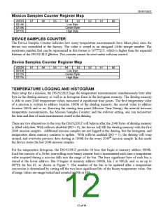
The setting of the RO bit (rollover enable) and sample rate depends on the duration of the mission and the
monitoring requirements. If the most recent temperature history is important, the rollover should be
enabled (RO = 1). Otherwise, one should estimate the duration of the mission in minutes and divide the
number by 2048 to calculate the value of the sample rate (number of minutes between temperature
conversions). If the estimated duration of a mission is 10 days (= 14400 minutes) for example, then the
2048-byte capacity of the datalog memory would be sufficient to store a new value every 7 minutes. If the
datalog memory of the DS1921H/Z is not large enough to store all temperature readings, one can use
several devices and set the Mission Start Delay to values that make the second device start recording as
soon as the memory of the first device is full, and so on. The RO-bit needs to be set to 0 to disable
rollover that would otherwise overwrite the recorded temperature log.
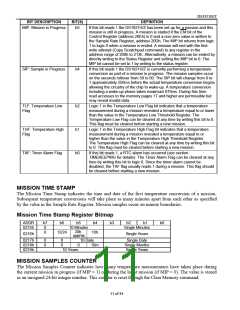
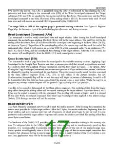
After the RO bit and the Mission Start Delay are set, the Sample Rate Register is the last element of data
that is written. The sample rate may be any value from 1 to 255, coded as an unsigned 8-bit binary
number. As soon as the sample rate is written, the DS1921H/Z will set the MIP flag and clear the
MEMCLR flag. After as many minutes as specified by the Mission Start Delay are over, the device will
wait for the next minute boundary, then wake up, copy the current time and date to the Mission Time
Stamp Register, and make the first temperature conversion of the mission. This increments both the
Mission Samples Counter and Device Samples Counter. All subsequent temperature measurements are
taken on minute boundaries specified by the value in the Sample Rate Register. One may read the
memory of the DS1921H/Z to watch the mission as it progresses. Care should be taken to avoid memory
access conflicts. See section Memory Access Conflicts for details.
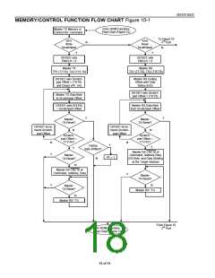
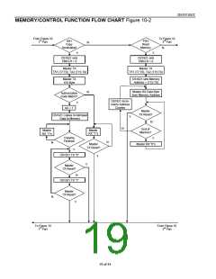
MEMORY/CONTROL FUNCTION COMMANDS
The Memory/Control Function Flow Chart (Figure 10) describes the protocols necessary for accessing
the memory and the special function registers of the DS1921H/Z. An example on how to use these and
other functions to set up the DS1921H/Z for a mission is included at the end of this document, preceding
the Electrical Characteristics section. The communication between master and DS1921H/Z takes place
either at regular speed (default, OD = 0) or at Overdrive Speed (OD = 1). If not explicitly set into the
Overdrive mode, the DS1921H/Z assumes regular speed. Internal memory access during a mission has
priority over external access through the 1-Wire interface. This can affect the Read Memory commands
described below. See section Memory Access Conflicts for details.
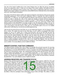
ADDRESS REGISTERS AND TRANSFER STATUS
Because of the serial data transfer, the DS1921H/Z employs three address registers, called TA1, TA2, and
E/S (Figure 9). Registers TA1 and TA2 must be loaded with the target address to which the data will be
written or from which data will be sent to the master upon a Read command. Register E/S acts like a byte
counter and transfer status register. It is used to verify data integrity with Write commands. Therefore, the
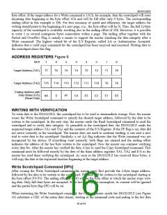
master only has read access to this register. The lower 5 bits of the E/S Register indicate the address of
the last byte that has been written to the scratchpad. This address is called Ending Offset. Bit 5 of the E/S
Register, called PF or “partial byte flag,” is set if the number of data bits sent by the master is not an
integer multiple of 8. Bit 6 is always a 0. Note that the lowest 5 bits of the target address also determine
the address within the scratchpad, where intermediate storage of data will begin. This address is called
15 of 44

 DALLAS [ DALLAS SEMICONDUCTOR ]