DS1921H/Z
byte sent by the master. This CRC is generated using the CRC16 polynomial by first clearing the CRC
generator and then shifting in the command code (0Fh) of the Write Scratchpad command, the Target
Addresses TA1 and TA2 as supplied by the master and all the data bytes. The master may end the Write
Scratchpad command at any time. However, if the ending offset is 11111b, the master may send 16 read
time slots and will receive an inverted CRC16 generated by the DS1921H/Z.
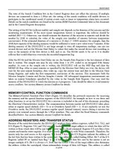
The range 200h to 213h of the register page is protected during a mission. See Figure 6, Register
Page Map, for the access type of the individual registers between and during missions.
Read Scratchpad Command [AAh]
This command is used to verify scratchpad data and target address. After issuing the Read Scratchpad
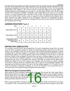
command, the master begins reading. The first 2 bytes will be the target address. The next byte will be the
ending offset/data status byte (E/S) followed by the scratchpad data beginning at the byte offset (T4:T0),
as shown in Figure 9. Regardless of the actual ending offset, the master may read data until the end of the
scratchpad after which it will receive an inverted CRC16 of the command code, Target Addresses TA1
and TA2, the E/S byte, and the scratchpad data starting at the target address. After the CRC is read, the
bus master will read logical 1s from the DS1921H/Z until a reset pulse is issued.
Copy Scratchpad [55h]
This command is used to copy data from the scratchpad to the writable memory sections. Applying Copy
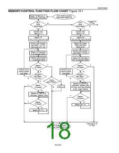
Scratchpad to the Sample Rate Register can start a mission provided that several preconditions are met.
See Mission Start and Logging Process description and the flow chart in Figure 11 for details. After
issuing the Copy Scratchpad command, the master must provide a 3-byte authorization pattern, which can
be obtained by reading the scratchpad for verification. This pattern must exactly match the data contained
in the three address registers (TA1, TA2, E/S, in that order). If the pattern matches, the AA
(Authorization Accepted) flag will be set and the copy will begin. A pattern of alternating 1s and 0s will
be transmitted after the data has been copied until the master issues a reset pulse. While the copy is in
progress any attempt to reset the part will be ignored. Copy typically takes 2µs per byte.
The data to be copied is determined by the three address registers. The scratchpad data from the begin-
ning offset through the ending offset will be copied, starting at the target address. Anywhere from 1 to 32
bytes may be copied to memory with this command. The AA flag will remain at logic 1 until it is cleared
by the next Write Scratchpad command. Note that Copy Scratchpad when applied to the address range
200h to 213h during a mission will end the mission.
Read Memory [F0h]
The Read Memory command may be used to read the entire memory. After issuing the command, the
master must provide the 2-byte target address. After the 2 bytes, the master reads data beginning from the
target address and may continue until the end of memory, at which point logic 0s will be read. It is im-
portant to realize that the target address registers will contain the address provided. The ending offset/data
status byte is unaffected.
The hardware of the DS1921H/Z provides a means to accomplish error-free writing to the memory sec-
tion. To safeguard data in the 1-Wire environment when reading and to simultaneously speed up data
transfers, it is recommended to packetize data into data packets of the size of one memory page each.
Such a packet would typically store a 16-bit CRC with each page of data to ensure rapid, error-free data
transfers that eliminate having to read a page multiple times to verify whether if the received data is cor-
rect. (See Application Note 114 for the recommended file structure.)
17 of 44

 DALLAS [ DALLAS SEMICONDUCTOR ]