DS1921H/Z
byte offset. If the target address for a Write command is 13Ch, for example, then the scratchpad will store
incoming data beginning at the byte offset 1Ch and will be full after only 4 bytes. The corresponding
ending offset in this example is 1Fh. For best economy of speed and efficiency, the target address for
writing should point to the beginning of a new page, (i.e., the byte offset will be 0). Thus, the full 32-byte
capacity of the scratchpad is available, resulting also in the ending offset of 1Fh. However, it is possible
to write 1 or several contiguous bytes somewhere within a page. The ending offset together with the
Partial and Overflow Flag is mainly a means to support the master checking the data integrity after a
Write command. The highest valued bit of the E/S Register, called AA or Authorization Accepted,
indicates that a valid copy command for the scratchpad has been received and executed. Writing data to
the scratchpad clears this flag.
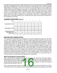
ADDRESS REGISTERS Figure 9
Bit #
7
6
5
4
3
2
1
0
Target Address (TA1)
T7
T6
T5
T4
T3
T2
T1
T0
Target Address (TA2)
T15
AA
T14
0
T13
PF
T12
E4
T11
E3
T10
E2
T9
E1
T8
E0
Ending Address with
Data Status (E/S)
(Read Only)
WRITING WITH VERIFICATION
To write data to the DS1921H/Z, the scratchpad has to be used as intermediate storage. First, the master
issues the Write Scratchpad command to specify the desired target address, followed by the data to be
written to the scratchpad. In the next step, the master sends the Read Scratchpad command to read the
scratchpad and to verify data integrity. As preamble to the scratchpad data, the DS1921H/Z sends the
requested target address TA1 and TA2 and the contents of the E/S Register. If the PF flag is set, data did
not arrive correctly in the scratchpad. The master does not need to continue reading; it can start a new
trial to write data to the scratchpad. Similarly, a set AA flag indicates that the Write command was not
recognized by the device. If everything went correctly, both flags are cleared and the ending offset
indicates the address of the last byte written to the scratchpad. Now the master can continue verifying
every data bit. After the master has verified the data, it has to send the Copy Scratchpad command. This
command must be followed exactly by the data of the three address registers TA1, TA2 and E/S as the
master has read them verifying the scratchpad. As soon as the DS1921H/Z has received these bytes, it
will copy the data to the requested location beginning at the target address.
Write Scratchpad Command [0Fh]
After issuing the Write Scratchpad command, the master must first provide the 2-byte target address,
followed by the data to be written to the scratchpad. The data will be written to the scratchpad starting at
the byte offset (T4:T0). The ending offset (E4:E0) will be the byte offset at which the master stops writ-
ing data. Only full data bytes are accepted. If the last data byte is incomplete, its content will be ignored
and the partial byte flag (PF) will be set.
When executing the Write Scratchpad command, the CRC generator inside the DS1921H/Z (see Figure
16) calculates a CRC of the entire data stream, starting at the command code and ending at the last data
16 of 44

 DALLAS [ DALLAS SEMICONDUCTOR ]