DS1921H/Z
BIT DESCRIPTION
BIT(S)
DEFINITION
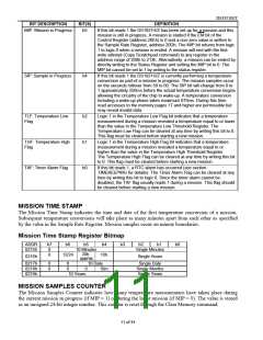
MIP: Mission in Progress
b5
If this bit reads 1 the DS1921H/Z has been set up for a mission and this
mission is still in progress. A mission is started if the EM bit of the
Control Register (address 20Eh) is 0 and a non-zero value is written to
the Sample Rate Register, address 20Dh. The MIP bit returns from logic
1 to logic 0 when a mission is ended. A mission will end with the first
write attempt (Copy Scratchpad command) to any register in the
address range of 200h to 213h. Alternatively, a mission can be ended by
directly writing to the Status Register and setting the MIP bit to 0. The
MIP bit cannot be set to 1 by writing to the status register.
SIP: Sample in Progress
b4
If this bit reads 1 the DS1921H/Z is currently performing a temperature
conversion as part of a mission in progress. The mission samples occur
on the seconds rollover from 59 to 00. The SIP bit will change from 0 to
1 approximately 250ms before the actual temperature conversion begins
allowing the circuitry of the chip to wake-up. A temperature conversion
including a wake-up phase takes maximum 875ms. During this time
read accesses to the memory pages 17 and higher are permissible but
may reveal invalid data.
TLF: Temperature Low
Flag
b2
b1
b0
Logic 1 in the Temperature Low Flag bit indicates that a temperature
measurement during a mission revealed a temperature equal to or lower
than the value in the Temperature Low Threshold Register. The
Temperature Low Flag can be cleared at any time by writing this bit to 0.
This flag must be cleared before starting a new mission.
THF: Temperature High
Flag
Logic 1 in the Temperature High Flag bit indicates that a temperature
measurement during a mission revealed a temperature equal to or
higher than the value in the Temperature High Threshold Register.
The Temperature High Flag can be cleared at any time by writing this bit
to 0. This flag must be cleared before starting a new mission.
TAF: Timer Alarm Flag
If this bit reads 1, a RTC alarm has occurred (see section
TIMEKEEPING for details). The Timer Alarm Flag can be cleared at any
time by writing this bit to logic 0. Since the timer alarm cannot be
disabled, the TAF flag usually reads 1 during a mission. This flag should
be cleared before starting a new mission.
MISSION TIME STAMP
The Mission Time Stamp indicates the time and date of the first temperature conversion of a mission.
Subsequent temperature conversions will take place as many minutes apart from each other as specified
by the value in the Sample Rate Register. Mission samples occur on minute boundaries.
Mission Time Stamp Register Bitmap
ADDR
0215h
b7
0
0
b6
b5
b4
b3
b2
b1
b0
10 Minutes
20h.
AM/PM
Single Minutes
12/24
10h.
0216h
Single Hours
0217h
0218h
0219h
0
0
0
0
10 Date
Single Date
Single Months
Single Years
0
10m.
10 Years
MISSION SAMPLES COUNTER
The Mission Samples Counter indicates how many temperature measurements have taken place during
the current mission in progress (if MIP = 1) or during the latest mission (if MIP = 0). The value is stored
as an unsigned 24-bit integer number. This counter is reset through the Clear Memory command.
11 of 44

 DALLAS [ DALLAS SEMICONDUCTOR ]