U631H16
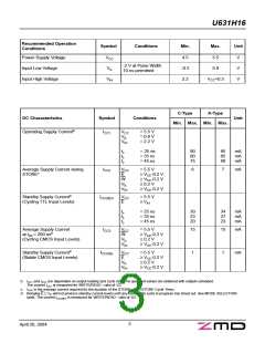
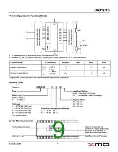
Recommended Operation
Conditions
Symbol
Conditions
Min.
Max.
Unit
Power Supply Voltage
Input Low Voltage
Input High Voltage
VCC
VIL
4.5
-0.3
2.2
5.5
0.8
V
V
V
-2 V at Pulse Width
10 ns permitted
VIH
VCC+0.3
C-Type
K-Type
DC Characteristics
Symbol
Conditions
Unit
Min. Max. Min. Max.
Operating Supply Currentb
ICC1
VCC
VIL
= 5.5 V
= 0.8 V
= 2.2 V
VIH
tc
tc
tc
= 25 ns
= 35 ns
= 45 ns
90
80
75
95
85
80
mA
mA
mA
Average Supply Current during
STOREc
ICC2
VCC
E
= 5.5 V
6
7
mA
≥ VCC-0.2 V
≥ VCC-0.2 V
≤ 0.2 V
W
VIL
VIH
≥ VCC-0.2 V
Standby Supply Currentd
(Cycling TTL Input Levels)
ICC(SB)1 VCC
E
= 5.5 V
≥ VIH
tc
tc
tc
= 25 ns
= 35 ns
= 45 ns
30
23
20
34
27
23
mA
mA
mA
Average Supply Current
at tcR = 200 nsb
ICC3
VCC
W
= 5.5 V
15
15
mA
≥ VCC-0.2 V
≤ 0.2 V
(Cycling CMOS Input Levels)
VIL
VIH
≥ VCC-0.2 V
Standby Supply Currentd
ICC(SB)
VCC
E
= 5.5 V
1
1
mA
(Stable CMOS Input Levels)
≥ VCC-0.2 V
≤ 0.2 V
VIL
VIH
≥ VCC-0.2 V
b: ICC1 and ICC3 are dependent on output loading and cycle rate. The specified values are obtained with outputs unloaded.
The current ICC1 is measured for WRITE/READ - ratio of 1/2.
c:
ICC2 is the average current required for the duration of the STORE cycle (STORE Cycle Time).
d: Bringing E ≥ VIH will not produce standby current levels until any nonvolatile cycle in progress has timed out. See MODE SELECTION
table. The current ICC(SB)1 is measured for WRITE/READ - ratio of 1/2.
3
April 20, 2004

 CYPRESS [ CYPRESS ]