SL811HS
5.3.6
USB Address Register, Reserved, Address [07H]
This register is reserved for the device USB Address in Slave operation. It should not be written by the user.
5.3.7
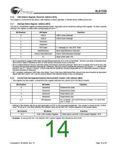
Interrupt Status Register, Address [0DH]
The ISR is a Read/Write register providing interrupt status. Interrupts can be cleared by writing to this register. To clear a specific
interrupt, the register is written with corresponding bit set to “1.”
Bit Position
Bit Name
USB-A
Function
0
1
2
3
4
5
6
7
USB-A Done Interrupt
USB-B Done Interrupt
USB-B
Reserved
Reserved
SOF timer
Insert/Remove
Device Detect/Resume
D+
1 = Interrupt on 1-ms SOF Timer
Slave Insert/Remove Detection
Device Detect/Resume Interrupt
Value of the Data+ Pin
• Bit 5 is provided to support USB cable Insertion/Removal for the SL811HS in Host Mode. This bit is set when a transition from
SE0 to IDLE (device inserted) or IDLE to SE0 (device removed) occurs on the bus.
• Bit 6 is shared between Device Detection status and Resume detection interrupt. When bit-6 of register 05H is set to one, this
bit will be the Resume detection Interrupt bit. Otherwise, this bit is used to indicate the presence of a Device, “1” = device “Not
present” and “0” = device “Present.” In this mode this bit should be checked along with bit 5 to determine whether a device
has been inserted or removed.
• Bit 7 provides continuous USB Data+ line status. Once it has been determined that a device has been inserted as described
above with bits 5 and 6, bit 7 can be used to detect if the inserted device is low- or full-speed.
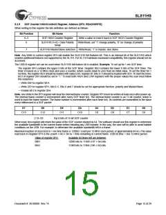
5.3.8
Current Data Set Register/Hardware Revision/SOF Counter LOW, Address [0EH]
• This register has two modes: a Read from this register indicates the current SL811HS silicon revision.
Bit Position
Bit Name
Reserved
Reserved
Reserved
Reserved
HW Revision
Function
0
1
Reserved for slave
Reserved for slave
Read will be zero
Read will be zero
2
3
4–7
SL11H Read = 0H, SL811HS rev1.2 Read = 1H, SL811HS
rev1.5 Read = 2
• Writing to this register will set up auto generation of SOF to all connected peripherals. This counter is based on the 12-MHz
clock. To set up a 1-ms timer interval, the software must set up both SOF counter registers to the proper values.
Bit Position
Bit Name
Function
0–7
SOF LOW Counter Register
Write-only to set SOF LOW Counter Register, OEH
• Example. To set up SOF for 1-ms interval, SOF counter register 0EH should be set to E0H.
Document #: 38-08008 Rev. *A
Page 14 of 29

 CYPRESS [ CYPRESS ]