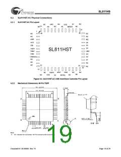
SL811HS
5.3.9
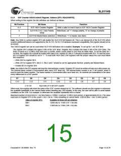
SOF Counter HIGH/Control2 Register, Address [0FH, READ/WRITE]
When writing to this register the bits definition are defined as follows.
Bit Position
Bit Name
Function
0–5
SOF HIGH Counter Register
Write a value or read it back to SOF HIGH Counter Register
6
SL811HS D+/D– Data Polarity
Write/Read, set “1” change polarity, “0” no change of polarity
Swap
7
SL811HS Master/Slave selection Write/Read, “1” is master, else Slave
Note. Any Write to control register 0FH will enable the SL811HS full features bit. This is an internal bit of the SL811HS which
enables additional features not supported by the SL11H. For SL11H hardware backward compatibility, this register should not be
accessed.
The USB-B register set can be used when SL811HS full feature bit is enabled. Example. To set up for 1-ms SOF time:
The register 0FH contains the upper 6 bits of the SOF timer. Register 0EH contains the lower 8 bits of the SOF timer. The
timer is based on a 12-MHz clock and uses a counter, which counts down to zero from an initial value. To set the timer for 1
ms time, the register 0EH should be loaded with value E0H, register 0F, Bits 0–5 should be loaded with 2EH. To start the timer,
bit 0 of register 05H should be set to “1.” To load both HIGH and LOW registers with the proper values the user must follow
this sequence:
— Write E0H to register 0EH.
— Write 2EH to register 0FH, bits 0–5. Bits 6 and 7 should be set for appropriate function: polarity and Master/Slave.
— Enable bit 0 in register 05H.
Note. Any Write to the 0FH register will clear the internal frame counter. Register 0FH must be written at least once after power-up.
The internal frame counter is incremented after every SOF timer tick. The internal frame counter is an 11-bit counter, which is
used to track the frame number. The frame number is incremented after each timer tick. Its contents are transmitted to the slave
every millisecond in a SOF packet.
D7
D6
D5
D4
D3
D2
D1
D0
C13
C12
C11
C10
C9
C8
C7
C6
C13–C6
Top 8 bits of 14-bit SOF counter.
When read, this register will return the value of the SOF counter divided by 64. The software should use this register to determine
the available bandwidth in the current frame before initiating any USB transfer. In this way, the user will be able to avoid babble
conditions on the USB. For example, to determine the available bandwidth left in a frame:
Maximum number of clock ticks in 1-ms time frame is 12000(1 count per 12-MHz clock period, or approximately 84 ns.) The value
read back in Register 0FH is the (count × 64) × 84 ns = time remaining in current frame. USB bit time = one 12-MHz period.
Value of register 0FH
Available bit times left are between
12000 bits to 11968 (187 × 64) bits
11968 bits to 11904 (186 × 64) bits
BBH
BAH
Document #: 38-08008 Rev. *A
Page 15 of 29

 CYPRESS [ CYPRESS ]