SL811HS
5.2.1
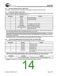
SL811HS Host Control Registers
Register Name SL11H and SL811H
SL11H (hex)
Address
SL811HS (hex)
Address
USB-A Host Control Register
00H
01H
00H
01H
02H
03H
04H
08H
09H
0AH
0BH
0CH
USB-A Host Base Address
USB-A Host Base Length
02H
USB-A Host PID, Device Endpoint (Write)/USB Status (Read)
USB-A Host Device Address (Write)/Transfer Count (Read)
USB-B Host Control Register
03H
04H
Reserved
Reserved
Reserved
Reserved
Reserved
USB-B Host Base Address
USB-B Host Base Length
USB-B Host PID, Device Endpoint (Write)/USB Status (Read)
USB-B Host Device Address (Write)/Transfer Count (Read)
5.2.2
USB-A/USB-B Host Control Registers [00H, 08H]
Bit Position
Bit Name
Arm
Function
0
1
Allows enabled transfers when set = “1.” Cleared to “0” when transfer is complete.
Enable
When set = “1” allows transfers to this endpoint. When set “0” USB transactions are ignored.
If Enable = “1” and Arm = '0' the endpoint will return NAKs to USB transmissions.
2
3
4
5
6
7
Direction
Reserved
ISO
When set = “1” transmit to Host. When “0” receive from Host.
When set to “1” allows Isochronous mode for this endpoint.
“1” = Synchronize with the SOF transfer
SOF
Data Toggle Bit “0” if DATA0, “1” if DATA1.
Preamble If set = “1” a preamble token is transmitted prior to transfer of low-speed packet. If set = “0,”
preamble generation is disabled.
• Bit 3 is reserved for future usage.
• The SL811HS uses bit 5 to enable transfer of a data packet after a SOF packet is transmitted. When this bit set “1,” the next
enabled packet will be sent after next SOF. If set = “0” the next packet is sent immediately if the SIE is free.
• The SL811HS automatically generates preamble packets when bit 7 is set. This bit is only used to send packets to a low-speed
device through a hub. To communicate to a full speed device, this bit is set to zero. For example, when SL811HS communicates
to a low-speed device via the HUB:
— SL811HS SIE should set to operate at 48 MHz, i.e., bit 5 of register 05H should be set = “0.”
— Bit 6 of register 0FH should be set = “0,” set correct polarity of DATA+ and DATA– state for Full Speed.
— Bit 7, Preamble Bit, should be set = “1” in Host Control register.
• When SL811HS communicates directly to low-speed device:
— SL811HS. Bit 5 of register 05H should be set = “1.”
— Bit 6 of register 0FH should be set = “1,” DATA+ and DATA– polarity for low speed.
— The state of bit 7 is ignored in this mode.
5.2.3
Example of SL811HS USB Packet Transfer
SL811HS memory set-up as shown:
03h-04h Register will contain PID and Device endpoint and Device Address.
10h-FFh USB Data as required.
Document #: 38-08008 Rev. *A
Page 10 of 29

 CYPRESS [ CYPRESS ]